
Page 205 - Subyek Computer Aided Design - [David Planchard] Engineering Design with SOLIDWORKS
P. 205
Engineering Design with SOLIDWORKS® 2018 Fundamentals of Assembly Modeling
, 1 /
-;Q::. To view the mates for more than one component, hold the Ctrl key down, select the
components, then right-click, and click the View Mates ~ tool.
A Mate problem displays the following icons:
& Warning. The mate is satisfied but is involved in over defining the assembly.
f3 Error. The mate is not satisfied.
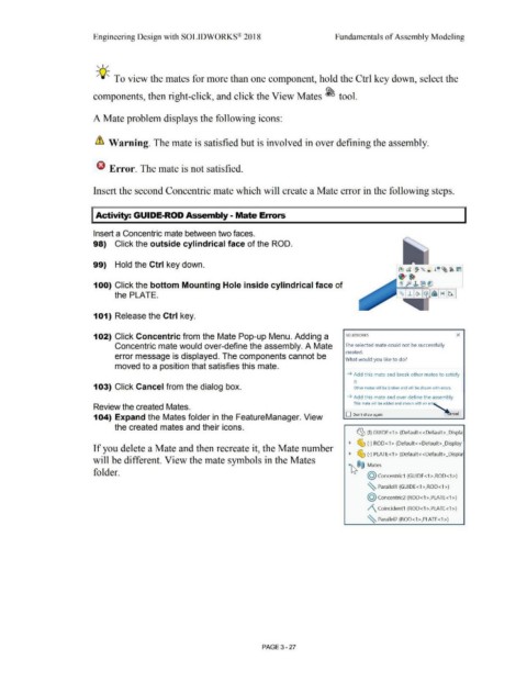
Insert the second Concentric mate which will create a Mate error in the following steps.
I Activity: GUIDE-ROD Assembly - Mate Errors
Insert a Concentric mate between two faces.
98) Click the outside cylindrical face of the ROD.
99) Hold the Ctrl key down.
100) Click the bottom Mounting Hole inside cylindrical face of
the PLATE.
101) Release the Ctrl key.
102) Click Concentric from the Mate Pop-up Menu. Adding a SOLIDWORKS X
Concentric mate would over-define the assembly. A Mate The selected mate could not be successfully
created.
error message is displayed. The components cannot be
What would you like to do?
moved to a position that satisfies this mate.
~ Add this mate and break other mates to satisfy
it
103) Click Cancel from the dialog box. Other mates will be broken and will be shown with errors.
~ Add this mate and over define the assembly
This mate will be added and shown with an err'
Review the created Mates.
104) Expand the Mates folder in the FeatureManager. View O Don't show again ~ ncel
the created mates and their icons.
~ (f} GUIDE <1 > (Default< <Default> _Displa
~ ~ (-) ROD<1> (Default<<Default>_Display
If you delete a Mate and then recreate it, the Mate number
~ ~ (-) PLATE<1 > (Default<<Default> _Displa:
will be different. View the mate symbols in the Mates
·~®@ Mates
folder.
@ concentric1 (GUIDE<1>,ROD<1>)
~ Parallel1 (GUIDE<1>,ROD<1>)
@ concentric2 (ROD<1 >,PLATE<1 >)
/\ Coincident1 (ROD<1 >,PLATE<1 >)
~ Parallel2 (ROD< 1>,PLATE<1>)
PAGE 3 - 27