
Page 203 - Subyek Computer Aided Design - [David Planchard] Engineering Design with SOLIDWORKS
P. 203
Engineering Design with SOLIDWORKS® 2018 Fundamentals of Assembly Modeling
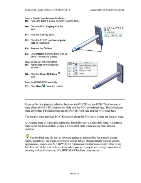
Insert a Parallel mate between two faces.
89) Press the Shift+ z keys to zoom in on the ROD.
90) Click the ROD Keyway Cut flat
face.
91) Hold the Ctrl key down.
92) Click the PLATE right rectangular
face as illustrated.
93) Release the Ctrl key.
94) Click Parallel from the Mate Pop-up
Menu. Parallel2 is created.
Clear all filters in SOLIDWORKS. :····: 9 ,._
• I :W: ~ ~ ~ -'="' - -~-,
95) Right-click in the Graphics L ... : [!] Toggle Selection Filters
window. P Z ~ C ear All Filters
J)J z 'llt- S ct All Filters
96) Click the Clear All Filters ~ p z [f;iJ Select
•
icon.
Save the GUIDE-ROD assembly.
97) Click Save II. View the results.
Mates reflect the physical relations between the PLATE and the ROD. The Concentric
mate aligns the PLATE Countersink Hole and the ROD cylindrical face. The Coincident
mate eliminates translation between the PLATE front face and the ROD back face.
The Parallel mate removes PLATE rotation about the ROD axis. Create the Parallel mate.
A Distance mate of O provides additional flexibility over a Coincident mate. A Distance
mate value can be modified. Utilize a Coincident mate when mating faces remain
coplanar.
, 1 /
-;Q~ Use the Pack and Go tool to save and gather all related files for a model design
(parts, assemblies, drawings, references, design tables, Design Binder content, decals,
appearances, scenes, and SOLIDWORKS Simulation results) into a single folder or zip
file. It is one of the best tools to utilize when you are trying to save a large assembly or
drawing with references and SOLIDWORKS Toolbox components.
PAGE 3-25