
Page 206 - Subyek Computer Aided Design - [David Planchard] Engineering Design with SOLIDWORKS
P. 206
Fundamentals of Assembly Modeling Engineering Design with SOLIDWORKS® 2018
Review the mates for a component.
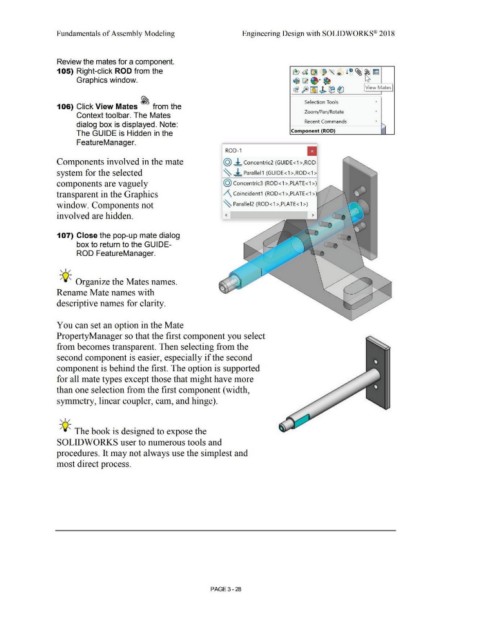
105) Right-click ROD from the ~ata l ~ ~l rm
~"' ®
Graphics window. ti ~ ~·~
~ft)~ ~ ®~ View Mates
I
Selection Tools •
106) Click View Mates ~ from the
Zoom/Pan/Rotate •
Context toolbar. The Mates
Recent Commands •
dialog box is displayed. Note: '
The GUIDE is Hidden in the Component (ROD)
FeatureManager.
II
ROD-1
Components involved in the mate @ ±. Concentric2 (GUIDE<1 >,ROD·
system for the selected ~ ~ Parallel1 (GUIDE<1 >,ROD<1 >I
components are vaguely @ concentric3 (ROD < 1 >,PLATE< 1 >)
transparent in the Graphics /\ Coincident1 (ROD<1 >,PLATE<1 >
window. Components not ~ Paralle12 (ROD<1 >,PLATE<1 >)
involved are hidden.
107) Close the pop-up mate dialog
box to return to the GUIDE-
ROD FeatureManager.
, ,/
-;Q~ Organize the Mates names.
Rename Mate names with
descriptive names for clarity.
You can set an option in the Mate
PropertyManager so that the first component you select
from becomes transparent. Then selecting from the
second component is easier, especially if the second
component is behind the first. The option is supported
for all mate types except those that might have more
than one selection from the first component ( width,
symmetry, linear coupler, cam, and hinge).
' I /
-;Q~ The book is designed to expose the
SOLIDWORKS user to numerous tools and
procedures. It may not always use the simplest and
most direct process.
PAGE 3 - 28