
Page 202 - Subyek Computer Aided Design - [David Planchard] Engineering Design with SOLIDWORKS
P. 202
Fundamentals of Assembly Modeling Engineering Design with SOLIDWORKS® 2018
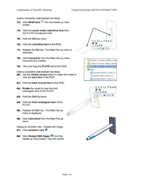
Insert a Concentric mate between two faces.
73) Click WireFrame ® from the Heads-up View
tool bar.
74) Click the center inside cylindrical face from
the PLATE Countersink hole.
75) Hold the Ctrl key down.
76) Click the cylindrical face of the ROD.
77) Release the Ctrl key. The Mate Pop-up menu is
displayed.
78) Click Concentric from the Mate Pop-up menu.
Concentric2 is created. ~ (f) GUIDE <1 > (Default< <Default> _Displc
~ ~ (-) ROD<1 > (Default< <Default> _Display
79) Click and drag the PLATE behind the ROD. ~ ~ (-) PLATE<1> (Default<<Default>_Displ,
..... ®@ Mates
Insert a Coincident mate between two faces.
@ concentric1 (GUIDE<1 >,ROD<1 >)
80) Use the middle mouse button to rotate the model to
~ Parallel1 (GUIDE<1 >,ROD<1 >)
view the back face of the ROD.
@ concentric2 (ROD<1 >,PLATE<1 >)
81) Click the back circular face of the ROD.
82) Rotate the model to view the front
rectangular face of the PLATE.
83) Hold the Ctrl key down.
84) Click the front rectangular face of the
PLATE.
85) Release the Ctrl key. The Mate Pop-up
menu is displayed.
86) Click Coincident from the Mate Pop-up
menu.
Display an Isometric view - Shaded with Edges.
87) Click Isometric view ~ .
88) Click Shaded With Edges ijJ from the
Heads-up View toolbar. View the results.
PAGE 3 - 24