
Page 199 - Subyek Computer Aided Design - [David Planchard] Engineering Design with SOLIDWORKS
P. 199
Engineering Design with SOLIDWORKS® 2018 Fundamentals of Assembly Modeling
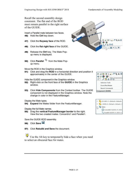
Recall the second assembly design
constraint. The flat end of the ROD
must remain parallel to the right surface
of the GUIDE.
•
•
Insert a Parallel mate between two faces. •
46) Hold the Ctrl key down.
47) Click the Keyway face of the ROD.
48) Click the flat right face of the GUIDE.
49) Release the Ctrl key. The Mate Pop-
up menu is displayed.
50) Click Parallel ~ from the Mate Pop-
up menu.
Move the ROD in the Graphics window.
51) Click and drag the ROD in a horizontal direction and position it
approximately in the center of the GUIDE. ~ al!i ~® i" ~~~
1$ ~ ~·
L. P [?fil t Hide Components
Hide the GUIDE component in the Graphics window. ~ - ~ ~ ~::iv
52) Right-click on the front face of the GUIDE in the Graphics Selection Tools •
window. Zoom/Pan/Rotate •
Recent Commands •
53) Click Hide Components from the Context toolbar. The GUIDE Component (GUIDE)
component is not displayed in the Graphics window. Note the
change in color in the FeatureManager.
Display the Mate types. ~ ~ (f} GUIDE<1 > (Default<<Default>_
54) Expand the Mates folder from the FeatureManager. ~ ~ (-) ROD<1> (Default<<Default>_C
~ ®@ Mates
Display the full Mate names.
@ concentric1 (GUIDE<1 >,ROD·
55) Drag the vertical FeatureManager border to the right.
~ Parallel1 (GUlDE<1>,ROD<1>
View the two created mates: Concentric1 and Parallel 1.
Save the GUIDE-ROD assembly.
56) Click Save ii.
57) Click Rebuild and Save the document.
, ,/
-;Q~ Use the Alt key to temporarily hide a face when you need
to select an obscured face for mates.
PAGE 3 - 21