
Page 204 - Subyek Computer Aided Design - [David Planchard] Engineering Design with SOLIDWORKS
P. 204
Fundamentals of Assembly Modeling Engineering Design with SOLIDWORKS® 2018
The mouse pointer displays the Filter ~'v icon when the Selection Filter is activated.
Deactivate Selection Filters when not required.
Activate/Deactivate Filters using the following keys:
Filter for ed ?:es Press e
Filter for faces Press x
Filter for vertices Press v
Hide/Show all Filters F5
Off/On all Selected Filters F6
Accidentally pressing thee, x or v keys can activate a Filter. If the mouse pointer displays
the Filter ~'v icon, you cannot select geometry, dimensions or text. Press the F5 key to
display the Selection Filter toolbar. Select Clear All Filters ~.
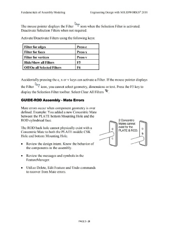
GUIDE-ROD Assembly - Mate Errors
Mate errors occur when component geometry is over
defined. Example: You added a new Concentric Mate
between the PLATE bottom Mounting Hole and the
ROD cylindrical face. 2 Concentric
Mates cannot
The ROD back hole cannot physically exist with a exist for the
0 PLATE & ROD.
Concentric Mate to both the PLATE middle CSK
Hole and bottom Mounting Hole. - '
-
• Review the design intent. Know the behavior of - . -
- ••
the components in the assembly.
• Review the messages and symbols in the
F eatureManager.
• Utilize Delete, Edit Feature and Undo commands
to recover from Mate errors.
PAGE 3-26