
Page 208 - Subyek Computer Aided Design - [David Planchard] Engineering Design with SOLIDWORKS
P. 208
Fundamentals of Assembly Modeling Engineering Design with SOLIDWORKS® 2018
Save the GUIDE-ROD assembly.
119) Click Save ii.
120) Click Rebuild and Save the document.
GUIDE-ROD Assembly - Modify Component Dimension
Modify part dimensions in the assembly. Utilize Rebuild to update the part and the
assembly. You realize from additional documentation that the Slot in the GUIDE is 4mm.
Modify the right Slot Cut feature dimensions in the GUIDE-ROD assembly. Rebuild the
assembly. The left Mirror Slot Cut and right Slot Cut update with the new value.
Activity: GUIDE-ROD Assembly - Modify Component Dimension
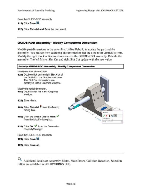
Modify the Slot of the Guide.
121) Double-click on the right Slot Cut of
the GUIDE in the Graphics window.
The Slot Cut dimensions are
displayed in the Graphics window.
Modify the radial dimension.
122) Double-click R3 in the Graphics • •
• •
window.
• •
123) Enter 4mm.
124) Click Rebuild I from the Modify
dialog box.
Modify
125) Click the Green Check mark ~
from the Modify dialog box.
126) Click OK ~ from the Dimension
PropertyManager.
Save the GUIDE-ROD assembly.
127) Click Save ii.
128) Click Save All.
~ Additional details on Assembly, Mates, Mate Errors, Collision Detection, Selection
Filters are available in SOLIDWORKS Help.
PAGE 3 - 30