
Page 212 - Subyek Computer Aided Design - [David Planchard] Engineering Design with SOLIDWORKS
P. 212
Fundamentals of Assembly Modeling Engineering Design with SOLIDWORKS® 2018
I GUIDE-ROD Assembly - Insert Mates for Flange Bolts
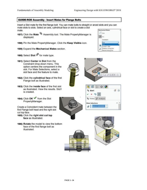
Insert a Slot mate for the first flange bolt. You can mate bolts to straight or arced slots and you can
mate slots to slots. Select an axis, cylindrical face or slot to create a slot
mate. Mechanical Mates
lolcam
157) Click the Mate ~ Assembly tool. The Mate PropertyManager is
displayed. I & ! slot
Constraint:
158) Pin the Mate PropertyManager. Click the Keep Visible icon.
I [ffl I C~~ter in Slot
159) Expand the Mechanical Mates section. ~ Distance Along Slot
~ Percent Along Slot
160) Select Slot & for mate type.
161) Select Center in Slot from the
Constraint drop-down menu. This
option centers the component in the
slot. For Mate Selections, select a
slot face and the feature to mate.
162) Click the cylindrical face of the first
Flange bolt as illustrated.
163) Click the inside face of the first slot ~1~ 1~1$ 1
as illustrated. View the results. Slot1
~ Slot1
is created.
~ x ~0
164) Click OK ~ from the Slot ~ Mates I If> Analysis I
PropertyManager.
Mate Selections
Create a Coincident mate between the
first Flange bolt head and the right slot
cut top face.
165) Click the right slot cut top
face as illustrated.
166) Rotate the model to view the bottom
face of the first flange bolt as
illustrated.
/ . ·
•
r
PAGE 3-34