
Page 214 - Subyek Computer Aided Design - [David Planchard] Engineering Design with SOLIDWORKS
P. 214
Fundamentals of Assembly Modeling Engineering Design with SOLIDWORKS® 2018
, ,/
-;Q~ Determine the static and dynamic behavior
Mechanical Mates
of mates in each sub-assembly before creating [Q]cam
the top level assembly. -
-
I (9 j Slot -
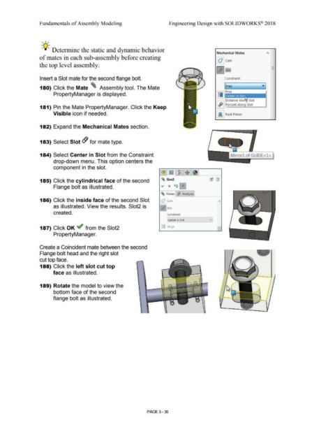
Insert a Slot mate for the second flange bolt. Constraint:
180) Click the Mate ~ Assembly tool. The Mate
PropertyManager is displayed. I fill I Fr: e.
Distance Alo Slot
I <ffJ I Percent Along Slot
181) Pin the Mate PropertyManager. Click the Keep
Visible icon if needed. I }l I Rack Pinion
182) Expand the Mechanical Mates section.
183) Select Slot & for mate type.
184) Select Center in Slot from the Constraint
drop-down menu. This option centers the
component in the slot.
~ ~ ~ $ @
-
~ Slot2
185) Click the cylindrical face of the second ., (JJ <i>
Flange bolt as illustrated. x t:t) 'It
~ Mates ~ Analysis
186) Click the inside face of the second Slot lO Jcam "
as illustrated. View the results. Slot2 is
!& !slot
created. Constraint:
Center in Slot vi
,
187) Click OK ~ from the Slot2 lillJ Hinge i
PropertyManager.
Create a Coincident mate between the second
Flange bolt head and the right slot
cut top face.
188) Click the left slot cut top
face as illustrated. -.
189) Rotate the model to view the
bottom face of the second
flange bolt as illustrated. - - -
PAGE 3 - 36