
Page 219 - Subyek Computer Aided Design - [David Planchard] Engineering Design with SOLIDWORKS
P. 219
Engineering Design with SOLIDWORKS® 2018 Fundamentals of Assembly Modeling
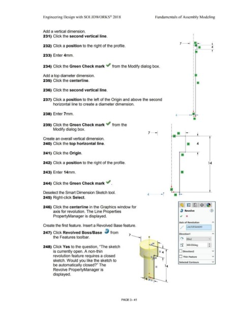
Add a vertical dimension.
231) Click the second vertical line.
7 - --
232) Click a position to the right of the profile. 4
t
233) Enter 4mm.
234) Click the Green Check mark ~ from the Modify dialog box.
Add a top diameter dimension.
235) Click the centerline.
236) Click the second vertical line.
237) Click a position to the left of the Origin and above the second
horizontal line to create a diameter dimension.
238) Enter 7mm. 4
239) Click the Green Check mark .; from the
Modify dialog box.
Create an overall vertical dimension.
240) Click the top horizontal line. 4
241) Click the Origin. f
242) Click a position to the right of the profile. 14
243) Enter 14mm.
244) Click the Green Check mark ~ .
Deselect the Smart Dimension Sketch tool. 4---r a
r -
245) Right-click Select.
c!& l~ l~l$ j~ J
246) Click the centerline in the Graphics window for
axis for revolution. The Line Properties lJ Revolve (1)
PropertyManager is displayed. .; x
Axis of Revolution A
,
Create the first feature. Insert a Revolved Base feature. .
, / 1Line1@Sketch1 I
.
247) Click Revolved Boss/Base ~ from Direction1 A
the Features toolbar. 0 v]
[ '°\. I 'Blind
·~ - t-
248) Click Yes to the question, "The sketch t:r 360.00deg ~
is currently open. A non-thin 1 4 D Direction2 v
revolution feature requires a closed ' .. --r D Thin Feature v
sketch. Would you like the sketch to
Selected Contours v
be automatically closed?" The
Revolve PropertyManager is
displayed.
PAGE 3 - 41