
Page 221 - Subyek Computer Aided Design - [David Planchard] Engineering Design with SOLIDWORKS
P. 221
Engineering Design with SOLIDWORKS® 2018 Fundamentals of Assembly Modeling
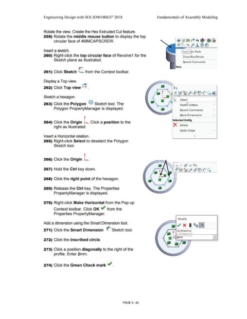
Rotate the view. Create the Hex Extruded Cut feature.
259) Rotate the middle mouse button to display the top
circular face of 4MMCAPSCREW. t$ ~ ~ ! ~ +, ~· ~ ~
~ro- (~ fo) J> ® ®
Insert a sketch. I Sketch ~n Tools
260) Right-click the top circular face of Revolve1 for the Zoom/Pan/Rotate
Sketch plane as illustrated.
Recent Commands
Face
261) Click Sketch (_ from the Context tool bar.
Display a Top view.
262) Click Top view @ . F-1
~ It lA5fi>~~(' ~efJ
Sketch a hexagon.
' I~ Sele~------'
263) Click the Polygon 0 Sketch tool. The Sketch Entities '
Polygon PropertyManager is displayed.
Recent Commands '
More Dimensions '
Selected Entity
264) Click the Origin L. Click a position to the
X Delete
right as illustrated.
Quick Snaps '
Insert a Horizontal relation.
265) Right-click Select to deselect the Polygon
Sketch tool.
266) Click the Origin L.
267) Hold the Ctrl key down.
268) Click the right point of the hexagon.
269) Release the Ctrl key. The Properties
PropertyManager is displayed.
270) Right-click Make Horizontal from the Pop-up
Context toolbar. Click OK ~ from the
Properties PropertyManager.
_ -l Modify
Add a dimension using the Smart Dimension tool.
271) Click the Smart Dimension (' Sketch tool.
~ Distance 1:=====1
¥-'42lmm 8
272) Click the inscribed circle.
273) Click a position diagonally to the right of the
profile. Enter 2mm.
274) Click the Green Check mark ~ .
PAGE 3 - 43