Page 223 - Subyek Computer Aided Design - [David Planchard] Engineering Design with SOLIDWORKS
P. 223

Engineering Design with SOLIDWORKS® 2018                                                                                                                                               Fundamentals of Assembly Modeling


                                                                        Coincident/Concentric SmartMate


                                                                        The most common SmartMate between a screw/bolt and a hole is the


                                                                        Coincident/Concentric SmartMate. The following technique utilizes two windows. The


                                                                        first window contains the 4MMCAPSCREW part and the second window contains the


                                                                        GUIDE-ROD assembly. Zoom in on both windows to view the Mate reference geometry.


                                                                        Drag the part by the shoulder edge into the assembly window. View the mouse pointer


                                                                        for Coincident/Concentric feedback ~&i. Release the mouse pointer on the circular edge


                                                                        of the PLATE Mounting Hole.


                                                                         Activity: Insert - Coincident/Concentric SmartMate


                                                                        Display the 4MMCAPSCREW part and the GUIDE-ROD assembly.


                                                                        281) Click Window, Tile Horizontally from the Menu bar.


                                                                        282) Zoom in on the PLATE to view the Mounting Holes.


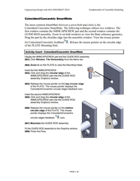
                                                                        Insert the first 4MMCAPSCREW.


                                                                        283) Click and drag the circular edge of the


                                                                                        4MMCAPSCREW part into the GUIDE-ROD                                                                                                                                                 Revolve!


                                                                                        assembly Graphics window.


                                                                        284) Release the mouse pointer on the top circular edge


                                                                                        of the PLATE. The mouse pointer displays the


                                                                                        Coincident/Concentric circular edges feedback icon.


                                                                        Insert the second 4MMCAPSCREW.


                                                                        285) Click and drag the circular edge of the


                                                                                        4MMCAPSCREW part into the GUIDE-ROD


                                                                                        assembly Graphics window.


                                                                        286) Release the mouse pointer on the bottom


                                                                                        circular edge of the PLATE. The mouse


                                                                                        pointer displays the Coincident/Concentric

                                                                                                                                                               ~ ~


                                                                                        circular edges feedback                                                     ~ icon.


                                                                        287) Maximize the GUIDE-ROD assembly.


                                                                        Fit the GUIDE-ROD assembly to the Graphics window.


                                                                        288) Press the f key.


                                                                                                                                                                                                        PAGE 3-45
   218   219   220   221   222   223   224   225   226   227   228