
Page 224 - Subyek Computer Aided Design - [David Planchard] Engineering Design with SOLIDWORKS
P. 224
Fundamentals of Assembly Modeling Engineering Design with SOLIDWORKS® 2018
, 1 /
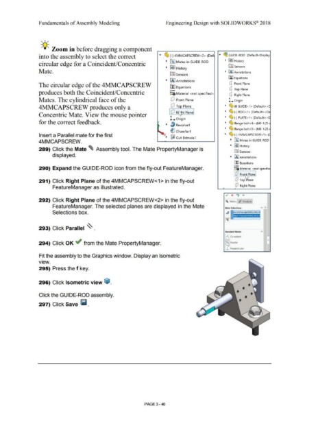
-;Q~ Zoom in before dragging a component
into the assembly to select the correct ... ~ (-) 4MMCAPSCREW<2> (Def .... ~ GUIDE-ROD (Default <Display
circular edge for a Coincident/Concentric • ~ Mates in GUIDE-ROD • ~J History
• ~ I History iflJ Sensors
Mate. • iAJAnnotations
~ Sensors
ilJ Equations
• LA I An notations
The circular edge of the 4MMCAPSCREW fl:J Equations dJ Front Plane
o- dJ Top Plane
produces both the Coincident/Concentric ~=ij. Material < not specified>
dJ Right Plane
Mates. The cylindrical face of the wJ Front Plane L Origin
4MMCAPSCREW produces only a wJ Top Plane • ~ (f)GUIDE<1> (Default< <C
Concentric Mate. View the mouse pointer I wJ Rept Planel • (g, (-) ROD<1 > (Default< <De
L Origin • ~ (-) PLATE<1 > (Default<<[
for the correct feedback. • ~ flange bolt<4> (M8-1.25:
• l, Revolve1
• ~ flange bolt<S> (M8-1.25:
~ Chamfer1
Insert a Parallel mate for the first .... (S, (-) 4MMCAPSCREW<1> (C
• ~ Cut-Extrude1
4MMCAPSCREW. • ~ Mates in GUIDE-ROD
• ~ J History
289) Click the Mate ~ Assembly tool. The Mate PropertyManager is
lnJ sensors
displayed.
• IAJ Annotations
EfJ Equations
o-
290) Expand the GUIDE-ROD icon from the fly-out FeatureManager. ~:a Material <not specifie
dJ Fro1 t Plane
291) Click Right Plane of the 4MMCAPSCREW<1> in the fly-out dJ Top rilane
FeatureManager as illustrated. dJ Right Plane
..,. x If) +
292) Click Right Plane of the 4MMCAPSCREW<2> in the fly-out ~ Mates ,$> Analysis
FeatureManager. The selected planes are displayed in the Mate Mate Selections A "
Selections box.
293) Click Parallel ~ .
Standard Matl!i
[ /\ Coincident
294) Click OK ~ from the Mate PropertyManager. L~ Parallel
j ..l Perpendicular
Fit the assembly to the Graphics window. Display an Isometric
•
view.
295) Press the f key.
296) Click Isometric view ~ .
Click the GUIDE-ROD assembly.
297) Click Save Iii.
PAGE 3-46