
Page 220 - Subyek Computer Aided Design - [David Planchard] Engineering Design with SOLIDWORKS
P. 220
Fundamentals of Assembly Modeling Engineering Design with SOLIDWORKS® 2018
Note: The ''Yes'' button causes a vertical line to be
automatically sketched from the top left point to the Origin.
The Graphics window displays a preview of the Revolved
Base feature.
rB CiCi ~ Rib ijj Wrap
i> Ci
249) Accept the default options. Click OK # from the Revolve Fillet Linear ~ Draft pD Intersect
Pattern
PropertyManager. Revolve1 is displayed in the
.. !'.. .. llaJ Shell !Ji.f!] Mirror
-
FeatureManager. > l"" \} Fillet J
. :,.
' ~-
Fit the model to the Graphics window. E(J Chamfer
250) Press the f key.
Insert a Chamfer feature.
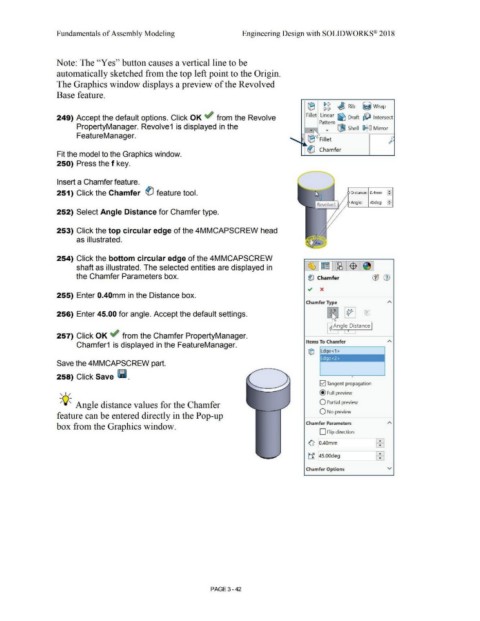
251) Click the Chamfer ® feature tool. Distance: 0.4mm f2
Angle: 45deg ~
252) Select Angle Distance for Chamfer type.
253) Click the top circular edge of the 4MMCAPSCREW head
as illustrated.
254) Click the bottom circular edge of the 4MMCAPSCREW
shaft as illustrated. The selected entities are displayed in
the Chamfer Parameters box. ~ Chamfer
255) Enter 0.40mm in the Distance box.
Chamfer Type
256) Enter 45.00 for angle. Accept the default settings. 0 ~ ®
-,A,-
. Angle Distance
.
257) Click OK ~ from the Chamfer PropertyManager.
Items To Chamfer
Chamfer1 is displayed in the FeatureManager.
C[j Edge<1 >
Edge<2> I
Save the 4MMCAPSCREW part.
258) Click Save lli. 0
!vi Tangent propagation
, 1 / @ Full preview
-;Q~ Angle distance values for the Chamfer O Partial preview
O No preview
feature can be entered directly in the Pop-up
Chamfer Parameters
box from the Graphics window.
D Flip direction
~ 0.40mm [: j
~ 45.00deg tR
Chamfer Options v
PAGE 3- 42