Page 225 - Subyek Computer Aided Design - [David Planchard] Engineering Design with SOLIDWORKS
P. 225

Engineering Design with SOLIDWORKS® 2018                                                                                                                                               Fundamentals of Assembly Modeling


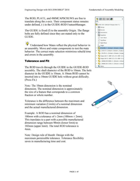
                                                                        The ROD, PLATE, and 4MMCAPSCREWS are free to                                                                                                                                                                ~l~ l~l$ i"'I                                                             >


                                                                        translate along the z-axis. Their component status remains                                                                                                                                                 v·


                                                                       under defined, (-) in the GUIDE-ROD FeatureManager.                                                                                                                                                        c:!fl GUIDE-ROD  (Default< Display State-1 >)


                                                                                                                                                                                                                                                                                    •  ~I History


                                                                        The GUIDE is fixed (f) to the assembly Origin. The flange                                                                                                                                                        ifi:J Sensors


                                                                                                                                                                                                                                                                                    • 00 Annotations
                                                                       bolts are fully defined since they are mated only to the


                                                                                                                                                                                                                                                                                         il'] Equations
                                                                        GUIDE.
                                                                                                                                                                                                                                                                                          [!]  Front Plane


                                                                          , 1,.                                                                                                                                                                                                           [!]  Top Plane


                                                                                                                                                                                                                                                                                          [!J  Right Plane

                                                                          -;Q~ Understand how Mates reflect the physical behavior in                                                                                                                                                     L  Origin


                                                                        an assembly. Move and rotate components to test the mate                                                                                                                                                    •  ~ (f} GUIDE<1 > (Default<<Default> _Display


                                                                       behavior. The correct mate selection minimizes rebuild time                                                                                                                                                  •  ~ (-) ROD<1 > (Default< <Default> _Display S


                                                                                                                                                                                                                                                                                    •  ~ (-) PLATE <1 > (Default< <Default> _Display
                                                                        and errors in the assembly.

                                                                                                                                                                                                                                                                                    •  ~ flange bolt<1> (MB-1.25 x 30<<M8-1.25 x


                                                                                                                                                                                                                                                                                    •  ~ flange bolt<2>  (M8-1.25 x 30<<M8-1.25 x

                                                                        Tolerance and Fit                                                                                                                                                                                           •  ~ (-)4MMCAPSCREW<1> (Default<<Defaul


                                                                                                                                                                                                                                                                                    •  ~ (-)4MMCAPSCREW<2> (Default<<Defaul


                                                                        The ROD travels through the GUIDE in the GUIDE-ROD                                                                                                                                                          •  ®®  Mates


                                                                        assembly. The shaft diameter of the ROD is lOmm. The hole


                                                                        diameter in the GUIDE is lOmm. A  lOmm ROD cannot be


                                                                        inserted into a 1  Omm GUIDE hole without great difficulty.


                                                                        (Press Fit.)


                                                                       Note: The lOmm dimension is the nominal


                                                                        dimension. The nominal dimension is approximately


                                                                        the size of a feature that corresponds to a common


                                                                        fraction or whole number.


                                                                        Tolerance is the difference between the maximum and


                                                                        minimum variation (Limits) of a nominal dimension


                                                                        and the actual manufactured dimension.


                                                                        Example: A ROD has a nominal dimension of


                                                                        lOOmm with a tolerance of± 2mm (lOOmm ± 2mm).


                                                                        This translates to a part with a possible manufactured


                                                                        dimension range between 98mm (lower limit) to


                                                                        102mm (upper limit). The total ROD tolerance is


                                                                        4mm.


                                                                       Note: Design rule of thumb: Design with the


                                                                        maximum permissible tolerance. Tolerance flexibility


                                                                        saves in manufacturing time and cost.


                                                                                                                                                                                                        PAGE 3- 47
   220   221   222   223   224   225   226   227   228   229   230