
Page 230 - Subyek Computer Aided Design - [David Planchard] Engineering Design with SOLIDWORKS
P. 230
Fundamentals of Assembly Modeling Engineering Design with SOLIDWORKS® 2018
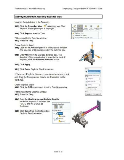
I Activity: GUIDE-ROD Assembly-Exploded View
Insert an Exploded view in the Assembly.
~
~
315) Click the Exploded View ~ --~ Assembly tool. The (S;··· ~ ~ wi ~
Exploded lnstant3D Update Take Large Assembl:
Explode PropertyManager is displayed.
View Speedpak Snapshot Mode
•
316) Click Regular step for Type. :: ~ ! E ~oded View
~~ Explode Line Sketch
Fit the model to the Graphics window. ~~ Insert/ Edit Smart Explode Lines
317) Press the f key.
y
Create Explode Step 1.
318) Click the PLATE component in the Graphics window.
The selected entity is displayed in the Settings box.
319) Enter 1 OOmm in the Explode distance box. The
direction of the explode view is towards the back. If
required, click the Reverse direction button.
320) Click Apply.
321) Click Done. Explode Step1 is created. Settings
If the exact Explode distance value is not required, click
ll:ll Z@GUIDE-ROD.SLDASM
and drag the Manipulator handle as illustrated in the
~ 100.00mm
next step.
11'+ II XYRing@PLATE-1
Create Explode Step2. ~ O.OOdeg
322) Click the ROD component from the Graphics window. ID Rotate about each
component origin
Fit the model to the Graphics window. O~OM A
323) Press the f key. [ Apply j I Done ]
324) Drag the blue/orange manipulator handle
backward to position between the
PLATE and the GUIDE as Explode Step Type
illustrated. ~ ~
325) Click Done from the Settings box. Explode Steps
Explode Step2 is created. 9 ~ Chain1
, i !el..
I _, ...... "'° PLATE-1
t ~ Chain2
' --- ~ ROD-1
PAGE 3-52