
Page 235 - Subyek Computer Aided Design - [David Planchard] Engineering Design with SOLIDWORKS
P. 235
Engineering Design with SOLIDWORKS® 2018 Fundamentals of Assembly Modeling
Save the Section View.
Save As x
356) Click Save from the Section _] Enable selection plane
View PropertyManager. The Preview J iv'i View orientation Save I
Save As dialog box is displayed.
"' *lso
SectionView is the default view Save as a view orientation D Drawing annotation view Cancel J
name. ' ~se_cti_on_Vie_w ____ ~I
View name:
357) Click Save.
PP~~ tA ~ I .I,© . <f) • ~ · Q ·
, t /
~
-;Q;, Click the drop-down arrow from the View v t:ifJ »
@ ~
•
Orientation tool as illustrated. Section View! is saved
~~~~
as a custom view.
@ J»
0 SectionView1
Display and Pin the View Orientation dialog box.
358) Press the space bar. View the Orientation box with the
•
new view.
359) Close ~ the Orientation dialog box.
Return to a full standard view.
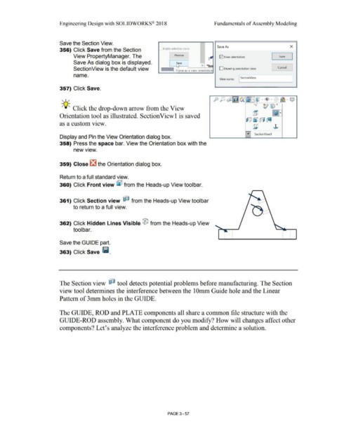
360) Click Front view [j;l from the Heads-up View toolbar.
361) Click Section view ~ from the Heads-up View tool bar
to return to a full view.
362) Click Hidden Lines Visible ® from the Heads-up View
tool bar.
Save the GUIDE part.
363) Click Save Ii.
The Section view ~ tool detects potential problems before manufacturing. The Section
view tool determines the interference between the IOmm Guide hole and the Linear
Pattern of 3mm holes in the GUIDE.
The GUIDE, ROD and PLATE components all share a common file structure with the
GUIDE-ROD assembly. What component do you modify? How will changes affect other
components? Let's analyze the interference problem and determine a solution.
PAGE 3- 57