
Page 236 - Subyek Computer Aided Design - [David Planchard] Engineering Design with SOLIDWORKS
P. 236
Fundamentals of Assembly Modeling Engineering Design with SOLIDWORKS® 2018
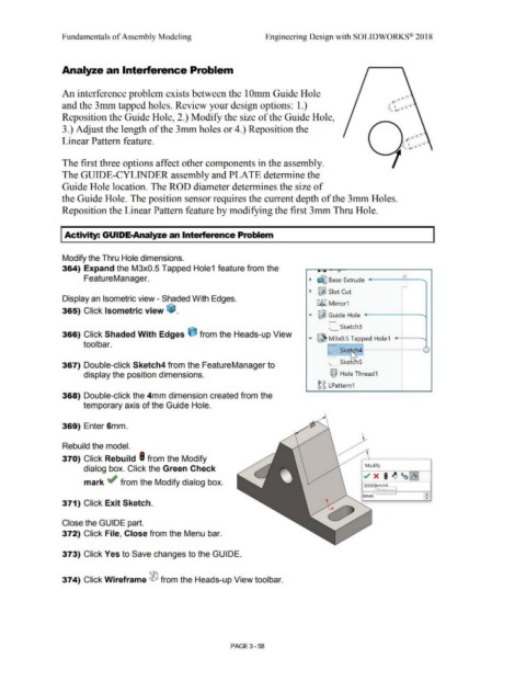
Analyze an Interference Problem
An interference problem exists between the 1 Omm Guide Hole
<
and the 3mm tapped holes. Review your design options: 1.) I , J J
.,
Reposition the Guide Hole, 2.) Modify the size of the Guide Hole,
3.) Adjust the length of the 3mm holes or 4.) Reposition the
Linear Pattern feature.
The first three options affect other components in the assembly.
The GUIDE-CYLINDER assembly and PLATE determine the
Guide Hole location. The ROD diameter determines the size of
the Guide Hole. The position sensor requires the current depth of the 3mm Holes.
Reposition the Linear Pattern feature by modifying the first 3mm Thru Hole.
Activity: GUIDE-Analyze an Interference Problem
Modify the Thru Hole dimensions.
364) Expand the M3x0.5 Tapped Hole1 feature from the - .
FeatureManager. ~ ~ Base Extrude ~ '
~
~ I&] Slot Cut
Display an Isometric view - Shaded With Edges.
~ ,(] M irror1
365) Click Isometric view ~ .
..... ~ Guide Hole '
L_ Sketch3
366) Click Shaded With Edges (j from the Heads-up View ..... ~ M3x0.5 Tapped Hole1 -
tool bar.
L_Ske~h4 ------------ ----- -
L_Sket1 hS
367) Double-click Sketch4 from the FeatureManager to
display the position dimensions. !Qi Hole Thread 1
~ ~ LPattern 1
368) Double-click the 4mm dimension created from the
temporary axis of the Guide Hole.
369) Enter 6mm.
Rebuild the model.
370) Click Rebuild I from the Modify
Modify
dialog box. Click the Green Check
mark ~ from the Modify dialog box. • 0 2@ ketch4
Distance,___ _ ___,_.....,.
.. 6m~ ~
371) Click Exit Sketch.
Close the GUIDE part.
372) Click File, Close from the Menu bar.
373) Click Yes to Save changes to the GUIDE.
374) Click Wireframe ® from the Heads-up View toolbar.
PAGE 3- 58