
Page 241 - Subyek Computer Aided Design - [David Planchard] Engineering Design with SOLIDWORKS
P. 241
Engineering Design with SOLIDWORKS® 2018 Fundamentals of Assembly Modeling
------.,....--.
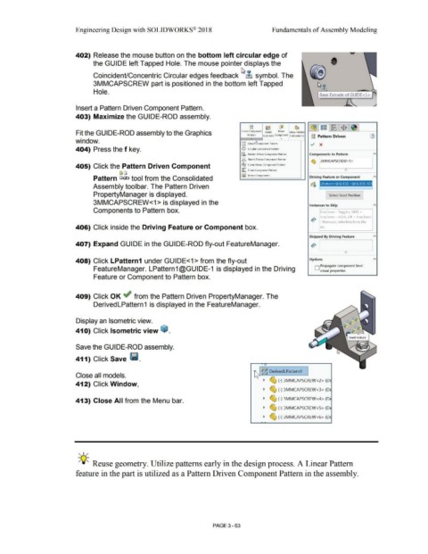
402) Release the mouse button on the bottom left circular edge of
the GUIDE left Tapped Hole. The mouse pointer displays the t
Coincident/Concentric Circular edges feedback ~ ~ symbol. The
3MMCAPSCREW part is positioned in the bottom left Tapped
Hole. ~
Base Extrude of GUIDE<l>
Insert a Pattern Driven Component Pattern.
403) Maximize the GUIDE-ROD assembly.
c, c,
l.l c, ~ ~ ~ ~ l~ l'll'6 :$ :~1
Fit the GUIDE-ROD assembly to the Graphics Ur>ear CompoMnt Smart Move Show Hidden
Patt em
. t-asteners Component C.omponents gg Pattern Driven (1)
.
window. Cl i;,
la i;, Lined~mporn;nt l'iJttem ./ x
"
404) Press the f key. "',:f Circular Component Patlem
~fu Pattern Driven Component Pattern Components to Pattern
, "'
:fl,.. Sk~ch Drive11 Compo11e11t PattMI\
~
13 M MCAPSCREW < 1 >
405) Click the Pattern Driven Component ~ C.11rv~ OrivPO C.omp0<1en1 Pnnpm I
~ Chain Component Pallern e
[J C;i
~l{) Mirror Components
Pattern C;i& tool from the Consolidated Driving Feature or Component "'
e,i ~l:Jffllll~l·l ~l·ll~·ll
21
Assembly toolbar. The Pattern Driven
PropertyManager is displayed. Select Seed Position ]
3MMCAPSCREW<1 > is displayed in the
Instances to Skip "'
Components to Pattern box. BoX/lasso - Toggles, Shift +
box/ldSSO Adds, All + box/lasso
.r,)
- Ren1oves, selection fron1 the
406) Click inside the Driving Feature or Component box. lisl.
"'
Skipped By Driving feature
407) Expand GUIDE in the GUIDE-ROD fly-out FeatureManager. -r,>
I I
0
408) Click LPattern1 under GUIDE<1 > from the fly-out Options "'
D Propagate component level
FeatureManager. LPattern1@GUIDE-1 is displayed in the Driving visual properties
Feature or Component to Pattern box.
409) Click OK ~ from the Pattern Driven PropertyManager. The
DerivedLPattern 1 is displayed in the FeatureManager.
Display an Isometric view.
41 O) Click Isometric view ~ .
Save the GUIDE-ROD assembly.
411) Click Save lf.M.
~ ~ DerivedLPattern1
Close all models.
~ ~ (-) 3MMCAPSCREW <2> (D
412) Click Window,
~ ~ (-) 3MMCAPSCREW<3> (D
413) Close All from the Menu bar. ~ ~ (-) 3MMCAPSCREW<4> (D
~ ~ (-) 3MMCAPSCREW<5> (D
~ ~ (-) 3MMCAPSCREW <6> (D
, 1 /
-;Q~ Reuse geometry. Utilize patterns early in the design process. A Linear Pattern
feature in the part is utilized as a Pattern Driven Component Pattern in the assembly.
PAGE 3- 63