
Page 242 - Subyek Computer Aided Design - [David Planchard] Engineering Design with SOLIDWORKS
P. 242
Fundamentals of Assembly Modeling Engineering Design with SOLIDWORKS® 2018
Review the Pattern Driven Component Pattern feature for the
3MMCAPSCREWs
You utilized the Save As/Save as copy and open option to copy the
4MMCAPSCREW to the 3MMCAPSCREW. The 3MMCAPSCREW was
mated to the GUIDE 3MM Tapped Hole. You utilized the Pattern Driven
Component Pattern tool to create an array of 3MMCAPSCREWs. The
Pattern Driven Component Pattern was derived from the GUIDE Linear
Pattern feature of Tapped Holes.
Linear Component Pattern Feature
Delete the second flange bolt. Utilize the Linear Component Pattern feature
to create an instance of the flange bolt. Additionally, the Linear Component
Pattern feature developed in the assembly is called LocalLPatternl. Note: If
you delete a mate and then recreate the mate, your instance number will be
different in the next activity.
I Activity: Linear Component Pattern
Delete the second flange bolt.
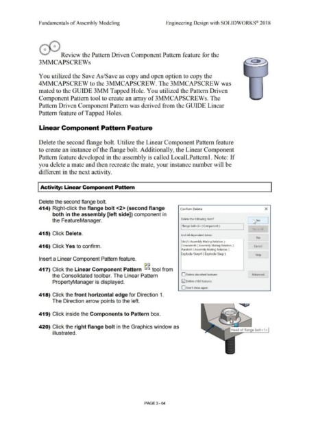
414) Right-click the flange bolt <2> (second flange Confirm Delet e x
both in the assembly [left side]) component in
the FeatureManager. Delete the following item? 1::s,ves
I flange bolt<2> (Component ) -
Yes tc, All
415) Click Delete. And all dependent items: -
No l
Slot2 ( Assembly Mating Relation. )
416) Click Yes to confirm. Coincident4 ( Assembly Mating Relation.) Cancel
Parallel4 ( Assembly Mating Relation. )
Explode Step4 ( Explode Step ) Help J
Insert a Linear Component Pattern feature.
[a~
417) Click the Linear Component Pattern ~ ~ tool from
the Consolidated tool bar. The Linear Pattern D Delete absorbed features Advanced
PropertyManager is displayed. G2] Delete child features
D Don't show again
418) Click the front horizontal edge for Direction 1.
The Direction arrow points to the left.
419) Click inside the Components to Pattern box.
420) Click the right flange bolt in the Graphics window as
illustrated.
PAGE 3 - 64