
Page 240 - Subyek Computer Aided Design - [David Planchard] Engineering Design with SOLIDWORKS
P. 240
Fundamentals of Assembly Modeling Engineering Design with SOLIDWORKS® 2018
The GUIDE Linear Pattern of 3mm tapped holes requires six 3MMCAPSCREW s. Do
you remember the seed feature in the Linear Pattern?
The first 3mm tapped hole is the seed feature. The seed feature is required for a
Component Pattern in the GUIDE-ROD assembly.
GUIDE-ROD Assembly - Pattern Driven Component Pattern
There are various tools to define a pattern in an assembly:
• Linear Component Pattern
Linear Component Smart Move Show Hidden
Pattern Fasteners Component Components
• Circular Component Pattern • • I
~ ~ Line ~Component Pattern
• Pattern Driven Component Pattern
!:a~~ Circular Component Pattern
• Sketch Driven Component Pattern ~t Pattern Driven Component Pattern
a
,;.!)~ Sketch Driven Component Pattern
• Curve Driven Component Pattern ~ Curve Driven Component Pattern
'h Chain Component Pattern
• Chain Component Pattern
C3l&J Mirror Components
• Mirror Components
Utilize the Pattern Driven Component Pattern tool to create instances of the
3MMCAPSCREW. Insert the 3MMCAPSCREW part into the GUIDE-ROD assembly.
I Activity: GUIDE-ROD Assembly-Pattern Driven Component Pattern
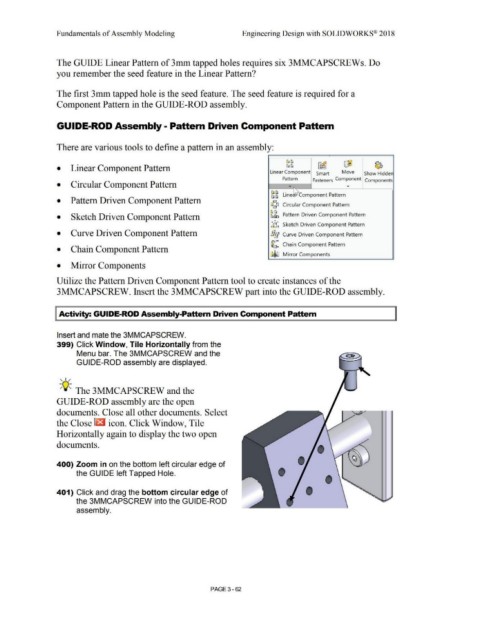
Insert and mate the 3MMCAPSCREW.
399) Click Window, Tile Horizontally from the
Menu bar. The 3MMCAPSCREW and the
GUIDE-ROD assembly are displayed.
, ,/
-;Q~ The 3MMCAPSCREW and the
GUIDE-ROD assembly are the open
documents. Close all other documents. Select "';:JJ·
the Close [t3 icon. Click Window, Tile
Horizontally again to display the two open
documents.
'
I
400) Zoom in on the bottom left circular edge of
the GUIDE left Tapped Hole.
'
401) Click and drag the bottom circular edge of I '
the 3MMCAPSCREW into the GUIDE-ROD
assembly.
PAGE 3-62