
Page 243 - Subyek Computer Aided Design - [David Planchard] Engineering Design with SOLIDWORKS
P. 243
Engineering Design with SOLIDWORKS® 2018 Fundamentals of Assembly Modeling
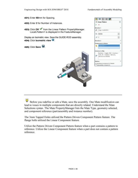
421) Enter 60mm for Spacing.
gg Linear Pattern
422) Enter 2 for Number of Instances.
Direction 1
423) Click OK ~ from the Linear Pattern PropertyManager. ~ ~IEd-ge-<l->@-Gu- 10-E--, ---~I
LocalLPattern 1 is displayed in the FeatureManager.
G 160.oom Ff
Display an Isometric view. Save the GUIDE-ROD assembly. }+i
424) Click Isometric view ~ . Direction 2 v
Components to Pattern
-- - -- -
425) Click Save Ii. flange bolt~
Instances to Skip "
Box/lasso - Toggles, Shift + box/lasso -
.!. Adds, Alt + box/lasso - Removes,
•o~ selection from the list.
Options
D Synchronize movement of flexible
subassembly components
, 1 /
-;Q~ Before you redefine or edit a Mate, save the assembly. One Mate modification can
lead to issues in multiple components that are directly related. Understand the Mate
Selections syntax. The Mate PropertyManager lists the Mate Type, geometry selected,
and component reference (part/assembly and instance number).
The 3mm Tapped Holes utilized the Pattern Driven Component Pattern feature. The
flange bolts utilized the Linear Component feature.
Utilize the Pattern Driven Component Pattern feature when a part contains a pattern to
reference. Utilize the Linear Component feature when a part does not contain a pattern
reference.
PAGE 3 - 65