
Page 245 - Subyek Computer Aided Design - [David Planchard] Engineering Design with SOLIDWORKS
P. 245
Engineering Design with SOLIDWORKS® 2018 Fundamentals of Assembly Modeling
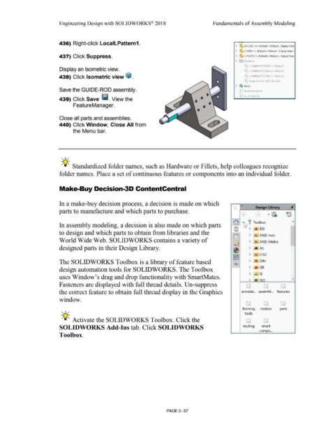
436) Right-click LocalLPattern1.
• ~ (f) GUIDE<1 > (Default<<Default> _Display State
• ~ (·) ROD<1 > (Oefault<<Oefault> _Display State 1
437) Click Suppress. • ~ (·) PLATE<1> (Oefault<<Oefault>_Oisplay State
• E;i I lardware
' (·) 3MMCAPSCREW <1 > (Default)
Display an Isometric view. F (·) 4MMCAPSCREW<2> (Default)
438) Click Isometric view ~ . (·) 4MMCAPSCREW<1> (Default)
i flange bolt< 1 > (M8· 1.25 x 30)
• O@ Mates
Save the GUIDE-ROD assembly. ~ ~ Derived LPattem 1
~ ~ LocalLPatternl
439) Click Save Ii. View the
FeatureManager.
Close all parts and assemblies.
440) Click Window, Close All from
the Menu bar.
, ,/
-;Q::. Standardized folder names, such as Hardware or Fillets, help colleagues recognize
folder names. Place a set of continuous features or components into an individual folder.
Make-Buy Decision-3D ContentCentral
In a make-buy decision process, a decision is made on which «
x Design Library
parts to manufacture and which parts to purchase.
"' [))\
~
~ f Toolbox
In assembly modeling, a decision is also made on which parts
@ > !lil BSI
to design and which parts to obtain from libraries and the
lo ) !l.l ANSI Inch
World Wide Web. SOLIDWORKS contains a variety of )
I~~ !:a ANSI Metric -
designed parts in their Design Library. ) MAS
~
) l!.I CISC
~
The SOLIDWORKS Toolbox is a library of feature based I;?;! ) ~ DIN
) ill GB
design automation tools for SOLIDWORKS. The Toolbox
> IS
uses Window's drag and drop functionality with SmartMates.
> m I 1so v
Fasteners are displayed with full thread details. Un-suppress D 0 D
the correct feature to obtain full thread display in the Graphics annotat... assembl... features
window.
0 D D
, ,/ forming motion parts
tools
-;Q::. Activate the SOLIDWORKS Toolbox. Click the D D
SOLIDWORKS Add-Ins tab. Click SOLIDWORKS routing smart
com po ...
Toolbox.
PAGE 3- 67