
Page 249 - Subyek Computer Aided Design - [David Planchard] Engineering Design with SOLIDWORKS
P. 249
Engineering Design with SOLIDWORKS® 2018 Fundamentals of Assembly Modeling
454) Enter GUIDE-ROD AND GUIDE-CYLINDER File name: CUSTOMER
ASSEMBLY for Description. Save as type: Assembly (*.asm;k.sldasm)
Description: !GUIDE-ROD AND GUIDE-CYLINDER ASSEMBLY
455) Click Save.
~ Save as 1cJ Include all referenced components
e) Save as copy and continue r Add prefix [
e) Save as copy and open 1 1 Add suffix I Advanced J
GUIDE-ROD is the first component in the
• Hide Folders
CUSTOMER assembly. Insert the second
component.
I Activity: CUSTOMER Assembly-Insert Component
Insert the MGPM12-1010 assembly.
456) Click the Insert Components be® Assembly tool. The
Insert Component PropertyManager is displayed. b~ ~ Cl Cl
Cl Cl
Insert Mate Cornponent Linear Compc
Com~ents " evrew Window Pattern
457) Click MGPM12-1010 from the Part/Assembly box. • •
?
( LaY, Insert Components
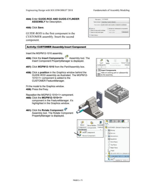
458) Click a position in the Graphics window behind the Adds an existing part or subassembly
GUIDE-ROD assembly as illustrated. The MGPM12- IJ8 to the assembly.
1010<1 > component is added to the
CUSTOMER FeatureManager.
Fit the model to the Graphics window.
459) Press the f key.
Reposition the MGPM12-1010<1> component.
460) Click the MGPM12-1010<1>
component in the FeatureManager. It's
highlighted in the Graphics window.
461) Click the Rotate Component <f
Assembly tool. The Rotate Component
PropertyManager is displayed.
~1~1~1$1~1 >
~ ~ ~
Move Show Hidden Assembl \(•
Component Components Feature ~ CUSTOMER (Default<Display StatE
...
• ~ J History
~ ... Mobt Cornponent
lfi:] Sensors
• fA] Annotations
Rotate Component
~ Equations
dJ Front Plane
dJ Top Plane
dJ Right Plane
l.... Origin
• ~ (f) GUIDE-ROD<1 > (Default<D
• I~(-) t ~PM12-1010<1> (MGPM
@@ M t"'\
a (-) MGPM12-1010<1 >
PAGE 3- 71