
Page 250 - Subyek Computer Aided Design - [David Planchard] Engineering Design with SOLIDWORKS
P. 250
Fundamentals of Assembly Modeling Engineering Design with SOLIDWORKS® 2018
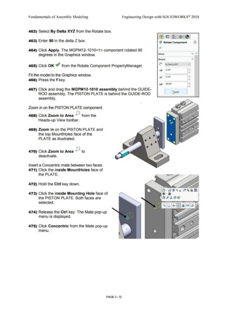
462) Select By Delta XYZ from the Rotate box.
~ ~ - ~ $ ~
463) Enter 90 in the delta Z box.
(I Rotate Component Ci)
~
464) Click Apply. The MGPM12-1010<1> component rotated 90
v ,..
degrees in the Graphics window. Move
Rotate A
c By Delta XYZ v
465) Click OK ~ from the Rotate Component PropertyManager.
t.X [ 0.00° I:
Fit the model to the Graphics window.
t.Y I 0.00° I:
466) Press the f key.
t.Z 190.00° I:
467) Click and drag the MGPM12-1010 assembly behind the GUIDE-
~ pply I
ROD assembly. The PISTON PLATE is behind the GUIDE-ROD I
(
assembly.
Zoom in on the PISTON PLATE component.
F\i
468) Click Zoom to Area ,..,, .. from the
Heads-up View toolbar.
469) Zoom in on the PISTON PLATE and
the top MountHoles face of the
PLATE as illustrated.
470) Click Zoom to Area {}, to
deactivate.
Insert a Concentric mate between two faces.
471) Click the inside MountHoles face of
the PLATE.
472) Hold the Ctrl key down.
et · d , ,~ t 0 ~~ ~
473) Click the inside Mounting Hole face of •••
the PISTON PLATE. Both faces are CB1 ft' J> ~ ~
selected.
474) Release the Ctrl key. The Mate pop-up
menu is displayed.
475) Click Concentric from the Mate pop-up
menu.
PAGE 3-72