
Page 254 - Subyek Computer Aided Design - [David Planchard] Engineering Design with SOLIDWORKS
P. 254
Fundamentals of Assembly Modeling Engineering Design with SOLIDWORKS® 2018
51 O) Click OK from the Browse For Folder dialog box.
Save the model.
511) Click Save. The CUSTOMER assembly remains open.
Close all files.
512) Click Windows, Close All from the Menu bar.
513) Click Yes. View the saved assembly in the CopiedModels folder.
>
~ CUSTOMER (Default<Display State-
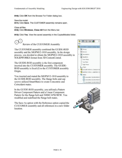
The CUSTOMER assembly combined the GUIDE-ROD • ~ -] History
assembly and the MGPM12-1010 assembly. In the design [0J Sensors
process, you decided to obtain the MGPM12-1010 assembly in • [A J Annotations
SOLIDWORKS format from 3D ContentCentral. [I] Equations
Q Front Plane
Q Top Plane
The GUIDE-ROD assembly is the first component
Q Right Plane
inserted into the CUSTOMER assembly. The GUIDE-
L. Origin
ROD assembly is fixed (f) to the CUSTOMER assembly
• ~ (f) GUIDE-ROD<1 > (Default<Dis
Origin.
• ~ MGPM12-1010<1 > (MGPM12-1C
.... ®@ Mates
You inserted and mated the MGPM12-1010 assembly to
@ concentric1 (GUIDE-ROD<1
the GUIDE-ROD assembly. The flange bolts and cap
@ concentric2 (GUIDE-ROD<1
screws utilized SmartMates to create Concentric and /\ Coincident1 (GUIDE-ROD<1
Coincident mates.
In the GUIDE-ROD assembly, you utilized a Pattern
Driven Component Pattern and a Linear Component
Pattern for the flange bolt and 3MMCAPSCREW. You
modified and redefined the flange bolt mates.
The Save As option with the Reference option copied the
CUSTOMER assembly and all references to a new folder
location.
PAGE 3-76