Page 257 - Subyek Computer Aided Design - [David Planchard] Engineering Design with SOLIDWORKS
P. 257

Engineering Design with SOLIDWORKS® 2018                                                                                                                                               Fund.amentals of Assembly Modeling


                                                                        Project Summary                                                                                                                                                                                                                                                                       >


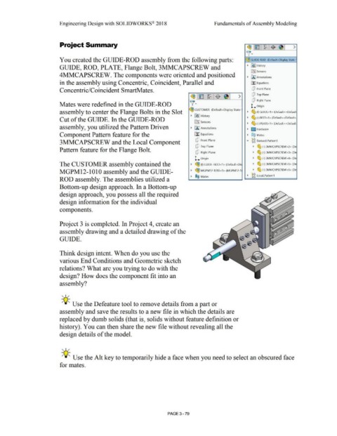
                                                                        You created the GUIDE-ROD assembly from the following parts:                                                                                                                                                                 ~ GUIDE-ROD  (Default<Display State-


                                                                        GUIDE, ROD, PLATE, Flange Bolt, 3MMCAPSCREW and                                                                                                                                                                                •  ~ I History


                                                                                                                                                                                                                                                                                                           iftl Sensors
                                                                        4MMCAPSCREW. The components were oriented and positioned
                                                                                                                                                                                                                                                                                                       •  iA] Annotations


                                                                        in the assembly using Concentric, Coincident, Parallel and                                                                                                                                                                         [I] Equations


                                                                        Concentric/Coincident SmartMates.                                                                                                                                                                                                   CJ  Front Plane


                                                                                                                                                                                                                                   ~l~ l~:-El71~1  >                                                        CJ  Top Plane


                                                                                                                                                                                                                                                                                                            CJ  Right Plane
                                                                        Mates were redefined in the GUIDE-ROD                                                                                                                      v'·                                                                     L  Origin


                                                                       assembly to center the Flange Bolts in the Slot                                                                                                            ~ CUSTOMER  (Default<Display State-                                  •  ~ (f) GUIDE<1> (Default<<Default


                                                                                                                                                                                                                                    •  ~      !History
                                                                        Cut of the GUIDE. In the GUIDE-ROD                                                                                                                                                                                             •  ~ (-) ROD<1> (Default<<Default>

                                                                                                                                                                                                                                        [0J Sensors
                                                                                                                                                                                                                                                                                                       •  ~ (-) PLATE<1> (Default<<Default
                                                                        assembly, you utilized the Pattern Driven                                                                                                                  • fAJ Annotations

                                                                                                                                                                                                                                                                                                      • l'.::J Hardware

                                                                        Component Pattern feature for the                                                                                                                               [fl Equations                                                  •  ®@  Mates


                                                                        3MMCAPSCREW and the Local Component                                                                                                                              Q Front Plane                                                ...  ~g  DerivedLPattern1


                                                                                                                                                                                                                                         Q Top Plane                                                         •  ~ (·) 3MMCAPSCREW<2> (DE
                                                                        Pattern feature for the Flange Bolt.

                                                                                                                                                                                                                                         Q Right Plane                                                       •  ~ (-) 3MMCAPSCREW<3> (DE


                                                                                                                                                                                                                                         L. Origin                                                           •  ~ (-) 3MMCAPSCREW<4> (DE

                                                                        The CUSTOMER assembly contained the                                                                                                                         •  ~ (f) GUIDE-ROD<1 > (Default<Di:                                      •  ~ (-) 3MMCAPSCREW<S>  (DE


                                                                        MGPM12-1010 assembly and the GUIDE-                                                                                                                         •  ~ MGPM12-1010<1> (MGPM12-1                                            •  ~ (-) 3MMCAPSCREW<6> (DE


                                                                                                                                                                                                                                                                                                       • ~ g LocalLPattern 1
                                                                                                                                                                                                                                    •  ®@  Mates
                                                                        ROD assembly. The assemblies utilized a


                                                                        Bottom-up design approach. In a Bottom-up


                                                                        design approach, you possess all the required


                                                                        design information for the individual


                                                                        components.


                                                                        Project 3 is completed. In Project 4, create an


                                                                        assembly drawing and a detailed drawing of the


                                                                        GUIDE.


                                                                        Think design intent. When do you use the


                                                                        various End Conditions and Geometric sketch


                                                                        relations? What are you trying to do with the


                                                                        design? How does the component fit into an


                                                                        assembly?


                                                                          , ,/


                                                                          -;Q~ Use the Defeature tool to remove details from a part or


                                                                        assembly and save the results to a new file in which the details are


                                                                        replaced by dumb solids ( that is, solids without feature definition or


                                                                       history). You can then share the new file without revealing all the


                                                                        design details of the model.


                                                                          , ,/


                                                                          -;Q~ Use the Alt key to temporarily hide a face when you need to select an obscured face


                                                                        for mates.


                                                                                                                                                                                                        PAGE 3- 79
   252   253   254   255   256   257   258   259   260   261   262