
Page 259 - Subyek Computer Aided Design - [David Planchard] Engineering Design with SOLIDWORKS
P. 259
Engineering Design with SOLIDWORKS® 2018 Fund.amentals of Assembly Modeling
Exercises
Exercise 3.1: Weight-Hook Assembly
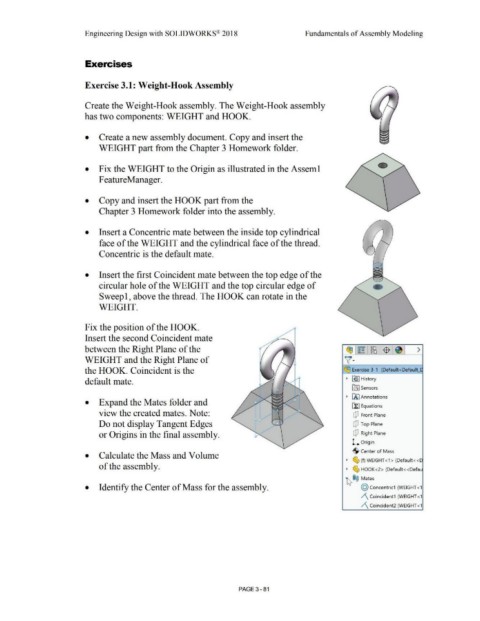
Create the Weight-Hook assembly. The Weight-Hook assembly
has two components: WEIGHT and HOOK.
• Create a new assembly document. Copy and insert the
WEIGHT part from the Chapter 3 Homework folder.
•
• Fix the WEIGHT to the Origin as illustrated in the Asseml
F eatureManager.
• Copy and insert the HOOK part from the
Chapter 3 Homework folder into the assembly.
• Insert a Concentric mate between the inside top cylindrical
face of the WEIGHT and the cylindrical face of the thread.
Concentric is the default mate.
• Insert the first Coincident mate between the top edge of the
circular hole of the WEIGHT and the top circular edge of
Sweep 1, above the thread. The HOOK can rotate in the
WEIGHT.
Fix the position of the HOOK.
Insert the second Coincident mate
between the Right Plane of the ~!~ I~!$ : ~I >
WEIGHT and the Right Plane of v·
the HOOK. Coincident is the ~ Exercise 3-1 (Default <Default_l
default mate. ~ ~J History
[a] Sensors
~ [A] Annotations
• Expand the Mates folder and
~ Equations
view the created mates. Note: CJ Front Plane
Do not display Tangent Edges CJ Top Plane
or Origins in the final assembly. CJ Right Plane
l. Origin
·$· Center of Mass
• Calculate the Mass and Volume
~ ~ (f) WEIGHT< 1 > (Default<< C
of the assembly. ~ ~ HOOK<2> (Default<<Defau
~ ®@ Mates
• Identify the Center of Mass for the assembly. @ concentric1 (WEIGHT <1
/\ Coincident1 (WEIGHT <1
/\ Coincident2 (WEIGHT <1
PAGE 3 - 81