
Page 262 - Subyek Computer Aided Design - [David Planchard] Engineering Design with SOLIDWORKS
P. 262
Fundamentals of Assembly Modeling Engineering Design with SOLIDWORKS® 2018
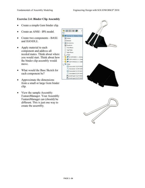
Exercise 3.4: Binder Clip Assembly
• Create a simple Gem binder clip.
,
~l~l~,$1~1 >
• Create an ANSI - IPS model.
v·
~ .,. Exercise 3.4 (Default<Displ
• Create two components - BASE ~I History
and HANDLE. lfl:] Sensors
• CA] Annotations
llJ Equations
• Apply material to each dJ Front Plane
component and address all dJ Top Plane
dJ Right Plane
needed mates. Think about where L Origin
you would start. Think about how • ~ ~ (f) CLIP-BASE <1 > (Defa
• ~ ~ CLIP- HANDLE<1 > (Defa
the binder clip assembly would
• ~ -- CLIP- HANDLE<2> (Defa
move. ~ 'O Mates
@ Concentric1 (CLIP-BASE
/\ Coincident1 (CLIP- BASE
• What would the Base Sketch for
@ Concentric3 (CLIP-BASE
each component be? /\ Coincident2 (CLIP- BASE
~ LimitAngle1 (CLIP-BASE
~ LimitAngle2 (CLIP-BASE
• Approximate the dimensions
from a small or large Gem binder
clip.
• View the sample Assembly
FeatureManager. Your Assembly
F eatureManager can ( should) be
different. This is just one way to
.....
create the assembly.
PAGE3 - 84