
Page 267 - Subyek Computer Aided Design - [David Planchard] Engineering Design with SOLIDWORKS
P. 267
Engineering Design with SOLIDWORKS® 2018 Fund.amentals of Assembly Modeling
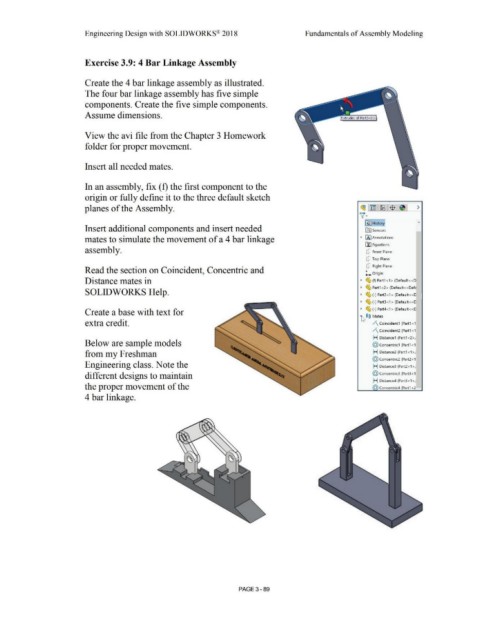
Exercise 3.9: 4 Bar Linkage Assembly
Create the 4 bar linkage assembly as illustrated.
The four bar linkage assembly has five simple
components. Create the five simple components.
Assume dimensions.
View the avi file from the Chapter 3 Homework
folder for proper movement.
Insert all needed mates.
In an assembly, fix (f) the first component to the
origin or fully define it to the three default sketch
planes of the Assembly. ~l~ I ~·1$ 1~1 >
\(•
~~-H-isto-ry]
Insert additional components and insert needed ifiJ Sensors -
mates to simulate the movement of a 4 bar linkage • IA] Annotations
[fl Equations
assembly. ct:J Front Plane
ct:J Top Plane
ct:J Right Plane
Read the section on Coincident, Concentric and
L. Origin
Distance mates in • ~ (f) Part1 <1 > (Default< <D
• ~ Part1 <2> (Default< <Defr
SOLIDWORKS Help. • ~ (·) Part2<1> (Default<<C
• ~ (·) Part3<1> (Default< <C
Create a base with text for • ~ (-) Part4<1> (Default<<C
~ ®@ Mates
extra credit. /\ Coincident1 (Part1 < 1
/\ Coincident2 (Part1 < 1
H Distance1 (Partl <2>,
Below are sample models @ concentric1 (Part1 < 1
from my Freshman H Distance2 (Part1 <1 >,I
@ concentric2 (Part2 < 1
Engineering class. Note the H Distance3 (Part2<1 >,I
different designs to maintain @ concentric3 (Part3 <1
H Distance4 (Part3 <1 >,l
the proper movement of the (0) Concentric4 (Part1 < 2
4 bar linkage.
PAGE 3- 89