
Page 268 - Subyek Computer Aided Design - [David Planchard] Engineering Design with SOLIDWORKS
P. 268
Fundamentals of Assembly Modeling Engineering Design with SOLIDWORKS® 2018
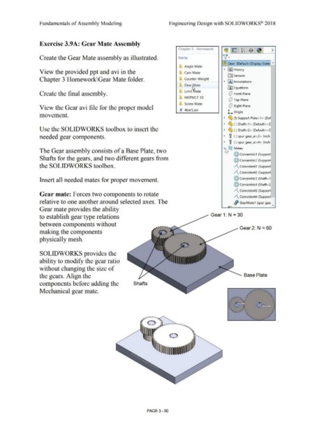
Exercise 3.9A: Gear Mate Assembly
Chapter 3 - Homework
~l~ l~:$ 1~1 >
Create the Gear Mate assembly as illustrated. Name v·
~ Gear (Default <Display State- "'
Angle Mate
View the provided ppt and avi in the Carn Mate • FE>] History
~ Sensors
Chapter 3 Homework\Gear Mate folder. Counter-Weight
• IA] Annotations
Gear ~ate
[fJ Equations
Create the final assembly. Limit 1t1ate [jJ Front Plane
MGPM12-10
[jJ Top Plane
Screw Mate
View the Gear avi file for the proper model [jJ Right Plane
~ 4barl.avi
L. Origin
movement.
• ~ (f) Support Plate<1 > (Def
• ~ (-) Shaft<1 > (Default < <C
Use the SOLIDWORKS toolbox to insert the • ~ (-) Shaft<2> (Default<<[
needed gear components. • f (-) spur gear_ai<2> (Inch
• f (-) spur gear_ai<4> (Inch
The Gear assembly consists of a Base Plate, two ·~®@ Mates
@ concentric1 (Support
Shafts for the gears, and two different gears from @ concentric2 (Support
the SOLIDWORKS toolbox. /\ Coincident 1 (Support
/\ Coincident2 (Support
Insert all needed mates for proper movement. @ concentric3 (Shaft<1
@ concentric4 (Shaft<2
/\ Coincident3 (Support
Gear mate: Forces two components to rotate
/\ Coincident4 (Support
relative to one another around selected axes. The - Ji GearMate1 (spur gea
Gear mate provides the ability "
to establish gear type relations Gear 1: N = 30
between components without
Gear 2: N = 60
making the components
physically mesh.
SOLIDWORKS provides the
ability to modify the gear ratio
without changing the size of
the gears. Align the Base Plate
components before adding the Shafts
Mechanical gear mate.
PAGE3 - 90