
Page 270 - Subyek Computer Aided Design - [David Planchard] Engineering Design with SOLIDWORKS
P. 270
Fundamentals of Assembly Modeling Engineering Design with SOLIDWORKS® 2018
8. Click OK ~ from the CamMateTangentl
PropertyManager. Mate Selections
Cam Path:
Insert a Coincident Cam follower mate.
~ I IFace<l >@cam-sJ
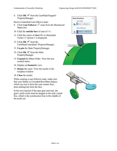
9. Click Cam Follower Cl mate from the Mechanical
Mates box. Cam Follower:
, ........................................................ '
10. Click the outside face of cam-s2<1>. . .
Vertex<l >@riser-1 \
...........................................................
11. Click the vertex of riser<l> as illustrated.
Vertex< l>@riser-1 is displayed.
12. Click OK ~ from the
CamMateCoincidentl PropertyManager.
Cam Follower
13. Un-pin the Mate PropertyManager.
14. Click OK ~ from the Mate
Property Manager.
15. Expand the Mates folder. View the new
created mates.
16. Display an Isometric view.
17. Rotate the cams. View the results in the
Graphics window.
18. Close the model.
When creating a cam follower mate, make sure
that your Spline or Extruded Boss/Base feature,
which you use to form the cam contact face,
does nothing but form the face.
In the next tutorial of the spur gear and rack, the
gear's pitch circle must be tangent to the rack's pitch
line, which is the construction line in the middle of
the tooth cut.
PAGE 3 - 92