
Page 275 - Subyek Computer Aided Design - [David Planchard] Engineering Design with SOLIDWORKS
P. 275
Engineering Design with SOLIDWORKS® 2018 Fund.amentals of Assembly Modeling
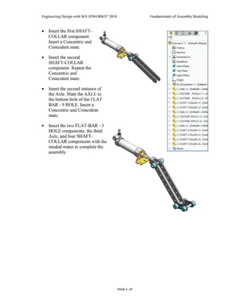
• Insert the first SHAFT -
~ ~ ~ -$- >
COLLAR component.
)[·
Insert a Concentric and ~ Exercise 3-11 (Default<Display
Coincident mate. ~ I History
ifi:J Sensors
• Insert the second • [A I Annotations
SHAFT-COLLAR [I] Equations
~ Front Plane
component. Repeat the
i:;? Top Plane
Concentric and
~ Right Plane
Coincident mate. 1.... Origin
• ~ (f) AirCylinder<1 > (Default<
• Insert the second instance of • ~ (-) Axle<1 > (Default<<Defa
the Axle. Mate the AXLE to • ~ (-) FLATBAR - 9HOLE <1> (D
the bottom hole of the FLAT • ~ (-) FLATBAR - 9HOLE<2> (D
• ~ (-) SHAFT-COLLAR< 1 > (Def
BAR - 9 HOLE. Insert a
• ~ (-) SHAFT-COLLAR<2> (Def
Concentric and Coincident
• ~ (-) Axle<2> (Default<<Defa
mate. • ~ (-) FLATBAR-3HOLE<1 > (De
• ~ (-) FLATBAR-3HOLE<2> (De
• Insert the two FLAT-BAR - 3 • ~ (-) Axle<3> (Default<<Defa
HOLE components, the third • (S; (-) SHAFT-COLLAR<3> (Def
Axle, and four SHAFT- • (S; (-) SHAFT-COLLAR <4> (Def
• (S; (-) SHAFT-COLLAR<S> (Def
COLLAR components with the
• (S; (-) SHAFT-COLLAR<6> (Def
needed mates to complete the
• ®@ Mates
assembly.
PAGE 3-97