
Page 274 - Subyek Computer Aided Design - [David Planchard] Engineering Design with SOLIDWORKS
P. 274
Fundamentals of Assembly Modeling Engineering Design with SOLIDWORKS® 2018
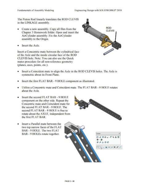
The Piston Rod linearly translates the ROD CLEVIS
in the LINKAGE assembly.
ROD
• Create a new assembly. Copy all files from the
CLEVIS
Chapter 3 Homework folder. Open and insert the
AirCylinder assembly. Fix the AirCylinder
assembly to the Origin.
• Insert the Axle.
Insert a Concentric mate between the cylindrical face
of the Axle and the inside circular face of the ROD
CLEVIS hole. Note: You can also use the Quick
mates procedure for all non-reference geometry
(planes, axes, points, etc.).
• Insert a Coincident mate to align the Axle in the ROD CLEVIS holes. The Axle is
symmetric about its Front Plane.
• Insert the first FLAT BAR - 9 HOLE component as illustrated.
• Utilize a Concentric mate and Coincident mate. The FLAT BAR - 9 HOLE rotates
about the Axle.
• Insert the second FLAT BAR - 9 HOLE
component on the other side. Repeat the
Concentric mate and Coincident mate for
the second FLAT BAR- 9 HOLE. The
second FLAT BAR- 9 HOLE is free to
rotate about the AXLE, independent from
the first FLAT BAR.
• Insert a Parallel mate between the
two top narrow faces of the FLAT
BAR- 9 HOLE. The two FLAT
BAR - 9 HOLEs rotate together. [ Default
.T. ! 0 ~ ~ ~
~ d J ~ ®
rBl ft ~ i:9 ~
PAGE3-96