
Page 280 - Subyek Computer Aided Design - [David Planchard] Engineering Design with SOLIDWORKS
P. 280
FundamentaJs of Drawing Engineering Design with SOLIDWORKS" 2018
• Rename parts and drawings.
• Insert a Center of Mass point.
Project Situation
The individual parts and assembly are completed. What is the next step? You are required
to create drawing.~ for various internal departments, nrunely production, purchasing,
engineering, inspection and manufacturing. Each drawing contains unique information
and specific footnotes. Example: A manufacturing drawing would require information on
assembly, Bill of Materials, fabrication techniques and references to other relative
docun1ents.
Project Overview
Generate two drawings in this project:
• GUIDE drawing with a cust01nized Sheet Format.
• GUIDE-ROD assembly drawing with a Bill of Materials.
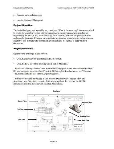
The GUIDE drawing contains three Standard Orthographic views and an Isometric view.
Do you remember what the three Principle Orthographic Standard views are? They are
Top, Front a11d Right side (Third Angle Projection).
Three new views are introduced in this project: Detailed view, Section view and
Auxiliary view. Orient the views to fit the drawing sheet. Incorporate the GUIDE
din1ensions into the drawing with inserted Annotations.
Detail View
' 3 -
-·- ....... ·- ' --
-
-' . .. -·-·-
Sectloo View ,,_, I
ISOfnetJlc View
' / •
TopVlew -+--•
....... .
't• ......
·- -· .. ,. --
'
' ',
Front View
I .)
•
A A
... t:..,. -· GUOE SUPPORT
'i -sizm2 A
•