
Page 285 - Subyek Computer Aided Design - [David Planchard] Engineering Design with SOLIDWORKS
P. 285
Engineering Design with SOLIDWORKS® 2018 Fundamentals of Drawing
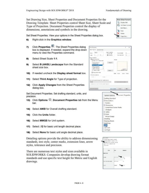
Set Drawing Size, Sheet Properties and Document Properties for the Sheet (Sheet Format1)
Drawing Template. Sheet Properties control Sheet Size, Sheet Scale and §i Display Grid
Type of Projection. Document Properties control the display of ~ Edit Sheet Format
Add Sheet. ..
dimensions, annotations and symbols in the drawing.
Ct) Copy
X Delete
Set Sheet Properties. View your options in the Sheet Properties dialog box.
6) Right-click in the Graphics window.
7) Click Properties ~ . The Sheet Properties dialog Sheet Properties ? x
box is displayed. If needed, expand the drop-down Sheet Properties Zone Parameters
menu to view the Properties command. Name: ._I She_et1 _ ___, Type of projection Next view label: I A
O First angle :==:::::::
Scale: 1, I : I 1 j @Third angle Next datum label: ._I A ___,
Sheet Format/Size
8) Select Sheet Scale 1: 1.
@ standard sheet size
Preview
O Only show standard format
A (ANSI) Landscape Reload
A (ANSI) Portrait
9) Select B (ANSI) Landscape from the Standard ,B (ANSI) Landscape
C (ANSI) Landscape
sheet size box. D (ANSI) Landscape
A I v
I b • landscape.slddrt Browse ...
1 O) If needed uncheck the Display sheet format box. 0 Display sheet format Width: 17.00in Heiaht: 11.00in
O Custom sheet size
V'/icl1 I I He1qht
11) Select Third Angle for Type of projection.
Use custom orooertv values from model shown in:
Default e~t Sh t to Mod, y
Same as sheet specified in Document Properties
12) Click Apply Changes from the Sheet Properties
dialog box.
Apply hanges Cancel Help
Set Document Properties. Set drafting standard, units, and
•
•
prec1s1on. System Options ocument Properties
Drafting Standard
13) Click Options @, Document Properties tab from the Menu l±lAnnotations
!
!
bar. i-·· Borders
ltl Dimensions
I Centerlines/Center Marks
14) Select ANSI for Overall drafting standard. l··· DimXpert
ffiTables
15) Click the Units folder. ffiViews
I Virtual Sharps
Detailing
16) Select MMGS for Unit system. Drawing Sheets
Grid/Snap
17) Select .12 for basic unit length decimal place.
ont
Line Style
18) Select None for basic unit angle decimal place.
Detailing options provide the ability to address dimensioning Unit system
O MKS (meter. kilogram. second)
standards, text style, center marks, extension lines, arrow -- ~ CGS (centimeter. gram. seco,.d)
MMGS (millimeter, gram, second)
01PS Qnch, pound, second)
styles, tolerance and precision. Ocustom
There are numerous text styles and sizes available in Type Unit Decimals
Basic Units
SOLIDWORKS. Companies develop drawing format -
standards and use specific text height for Metric and English Length mmimetflrs .12~ -
'
drawings. Dual Dirnension Length millimeters .12
Angle degrees ~ one
PAGE4-9