
Page 284 - Subyek Computer Aided Design - [David Planchard] Engineering Design with SOLIDWORKS
P. 284
Fundamentals of Drawing Engineering Design with SOLIDWORKS® 2018
7. ? .. D x
Jj5 SOLIDWORKS File Edit View Insert Tools Window Help ;,t [j ·~ ·ii·~ .. ·fil] . 8 • -
(' ~ A~ # A AAA JD Balloon ef Surface Finish lol031 Geometric Tolerance ~
AAA
. Sma~ Model Spell Format Note Linear Note ~ Auto Balloon fY< Weld Symbol ~ Blocks ))
Datum Feature
Dimension Items Checker Painter Pattern n
.. .. ......., Magnetic Line U0 Hole Callout fiiJ Datum Target ..
. . . . . . . .. . . . .. . • • . • • . - . . . - .. ...
View Layout Annotation Sketch Evaluate SOLIDWORKS Add-Ins Sheet Format
. • I. I 0 I 2 D [] - 6l x
.
- pppJ~ ~ ..
.
. ~ l~ I > · @
. \(
. I (o)
. ;..
. 00 Annotations @)
.
....._ 4Je eDrawings M arkups - lo
......
~ ,~~
D Sheet1
.
.....
. ~ Sheet Format1
. ~
.
~ ~ General Table ~
. ~
. ~ Bill of Materia e
. l;q
-
. ~ Hole Table Ar
.
.
Eli, Weldment Cu
.
. ~ Revision Tabl,
.
Eifi, Weld Table A,
.
. A
. ~ Bend Table Ar u1o,n1 o ... ,.,..u, nn:.rn • 1o-r .L ......
(1, .. -..,.., .. N' .... 4""
'OI"-'"""° Ot.,'"'lo_ Tat.f ;
..... .,oi,,,, :
~
. ~~:.::;;:.: .• '7 I fl,<, ,# .. ' , .
-l'T*l;,(.l'(l, f.: ..... , •
. ~ Punch Table/. ...-.. ~ ... --- ..IC, .. -
_ ", .. "_
. • ... M0""" '> "°""'"- ...... ... .. .,... .. ~
c.o .... ,,.. ••
-Vf Kf .. <,0""'1>1•••1
l[.J Border1 c,t,. ..... C,Oil•WOt rHO~OI -· U!t ~ W (I . H (). t IV
<.1of'¥.:.-.-... ..,.- . ~··
... -,--.... "'"-··
. c•tOOICTClh " t.,• 0 1.oJ ,. - - ""'"" .. ,n~ B Drawl
"""""'"'r---"
\; ·-- ..... .:; .. ~ .. f
. IH 1'"41,t lif.o ......... _ fc.All: 1!1 W'flOKf: 1H£U 1 ¢,f 1
. I
< > 4 3 2 1
. ~1~i•l'1>- Di '-'
. Sheet1
. ..
...
;oLIDWORKS Premium 2018 x ... 2.32in 4.69in Oin Under Defined Editinq Sheet1 1 : 1 • IPS ~ •
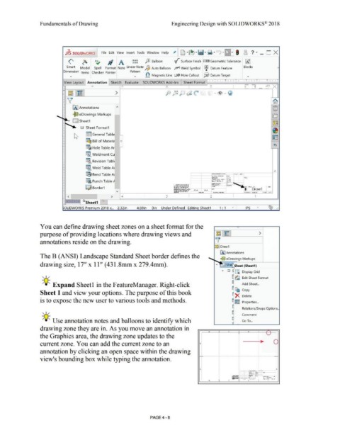
You can define drawing sheet zones on a sheet format for the
purpose of providing locations where drawing views and ~ l~I >
annotations reside on the drawing. 'v
I~~ Draw1
IA] Annotations
The B (ANSI) Landscape Standard Sheet border defines the
,..__. 9le eDrawings Markups
drawing size, 17'' x 11'' (431.8mm x 279.4mm). She heet (Sheet1)
sr D S lffl, Display Grid
, ,/
~ ~ Edit Sheet Format
~
-;Q~ Expand Sheetl in the FeatureManager. Right-click Add Sheet ...
~ [b Copy
Sheet 1 and view your options. The purpose of this book
~x Delete
is to expose the new user to various tools and methods. ~ ~ p rt•
ia rope 1es ...
e -
Relations/Snaps Options ..
, ,/ ~ Comment
-;Q~ Use annotation notes and balloons to identify which Go To ...
drawing zone they are in. As you move an annotation in
• I " I ? I f '
the Graphics area, the drawing zone updates to the ' '-../
•
•
•
•
•
• > 0
•
current zone. You can add the current zone to an & •
•
•
•
•
•
annotation by clicking an open space within the drawing •
•
•
•
,_ - ------------------------------·----------------- --------------
•
view's bounding box while typing the annotation. •
•
•
•
•
•
•
•
•
•
A • A
•
~:--· :::. . ·-
w --··-.... - r4 ::::::i
--· ... -
=:..."':' ~- 1-l
'&~ ~ ... .... - - 1~ -* - 1
-
"";"°~ ::...c.
- --
"'""'=;;
C>row.l
I
9
~--- · _ ..,. 2 ..,,....,,.., ' I - .. j.. ·-·· ·
4 I 3
PAGE4 -8