
Page 281 - Subyek Computer Aided Design - [David Planchard] Engineering Design with SOLIDWORKS
P. 281
Engineering Design with SOLIDWORKS® 2018 Fundamentals of Drawing
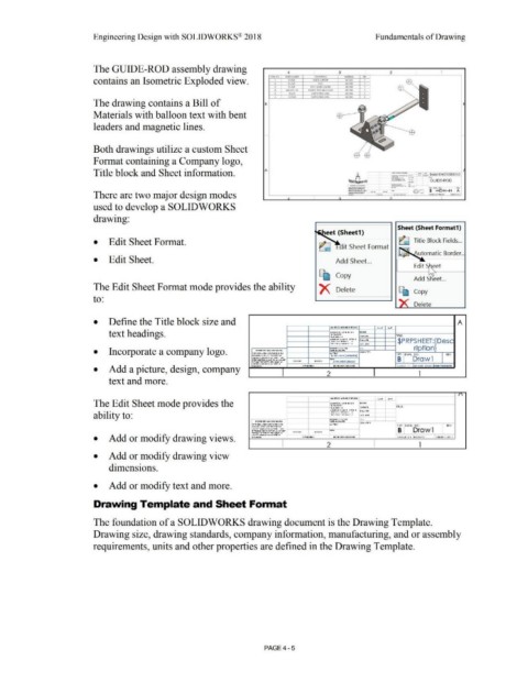
The GUIDE-ROD assembly drawing
4 3 2 1
... ..,.
IEMNO. PAl't NUNAEI OUCRtP.I IC>H MAIER"-~ °''·
contains an Isometric Exploded view. , ....... GUIDf su,,011 ,i,Gl304 I I
I
•
ROD
$'-A11
Alitll'M
-
PIAltS~dlMM
I
A51304
' Nl&-l.2Sx XI tlAkC( IOU N&.1.2Sot:Xl AIH30,. 2
•
/\61>04
C:N SCIUW, .. WM
2
' , .. 4'3A CAP SCP.:(W )MY! A1Sf30I '
The drawing contains a Bill of B
Materials with balloon text with bent
leaders and magnetic lines.
Both drawings utilize a custom Sheet
Format containing a Company logo,
Title block and Sheet information. A ......... _, "«- - ... ,,,.,..,. D&M CNC JNEERINO
-·
..........
-·-··--.. - ... ·-·
-... ...,. __ , ...
-~-·-(·•"" .......
_ ....... ~··· --· ""
-···· GUIDE-ROD
There are two major design modes
used to develop a SOLIDWORKS
drawing:
Sheet (Sheet Format1)
eet (Sheet1)
• Edit Sheet Format . ait Sheet Format ~ Title Block Fields ...
utomatic Border ..
• Edit Sheet . Add Sheet ...
[b Copy
Add Sheet. ..
The Edit Sheet Format mode provides the ability X Delete ~ Copy
to:
Delete
• Define the Title block size and A
1W11SS Ot•I rwl!il S PCHED: ....... r ··~
text headings. D ... n-s 01o i .-.,r .... c. .. n .,.,.w,. Tl lf:
,o,in,,.,.c.n ·
'""'r,..
rt .. c.,a .... 1 t
... c.111 .. , , ... ,.c. .. : • n,c, : r iot.,,. PW
PWQ fhC.r t l"C.WJII • $PRPSHEET:{Desc
, ... ttT'PL,,,r tl'C.H ,.t l .. ,c. .......
,..,,w."'" c.ro .. ,...c. •• ription}
• Incorporate a company logo. '"'"IIOt w,.•IQt, , o.,r,o41o1'11 " 11,,11: °""'""""""' ..,.. c.o ..... n-,,•
"~"' • "" IIJ•O c.c.ncin, 'l• t
........... t
• e .. w•c. .:.-.,rsotr KOtR"''ro, ... SaE DWC. NO. IEV
i P RP1 HEfl{M:ll« rio l}
c. .. ,:,... co.,. .. ,., .. _ r1on-r, ..... .,
.. l'H'O(UJ,.•11:11> " ,_.~ Ot "'' '"W1oOlr .. Ill , ... -» ... 1) 10 0,t B Drawl
""""ou, ,w "'"'""' ,n-,.,1u_,. or HOPSHf!l:{Anlsn}
d•{ f'lf co .... ............. ,. .. ,,...~ ti ..... ..c ... ,o .. 00 <)U C" ... t tOl>V>MO- 1 CALE'. l '.1 lAlf: ICHT: u u1 ilm1~
, tll1o1Jn
• Add a picture, design, company
2 l
text and more.
r\
....... r T ,,~
f 11>11 GS O M ""'GlS tt: HlO:
The Edit Sheet mode provides the o ..,n,, "", ..otr " "' "" ' Ot...V ..
•0 1~ ... ,."'1·
,,,.c..•ro1o ... , • c.1orc.r111 - TILE'.
, noo :
.. " " u1, .. , . ,.. ... ' " : • r .. c. _.,,,
•wo H ... c.r• rc..., .. 1
ability to: •1-trTtt..c.r orc.w .. , :t. ... re. ... ,.. I
" ' rn,K"c.l'O..-~ C ., 0 '
ltetK• ,U 'I' .U.0 .COlltlrLlo ll6t •ou·• .. 1-e• c. lff'· c..o .... n.,,,
..,.,....ro,-.. ... ,01- , o,.• ... 11ot11 " "'' ...... ,m.., , ev
• "'"'"" 11 •1-rso1r tte1,n,,.or sae DINO. MO .
..... 111" eo .. ,.,.,.,.1-... ..-r 1-n n ..... ,. , ... _ ..
HM•OCIU.:.•cs, " ,_.,., Cit ... , ..,w s,0 1r B Drawl
.. 11<,,..sv d t llO of
h"'"'011••M' "'"''"' ,,,, ... ,o .. Cit
., .. SA"" co .. ,,...., .. ,..,..,. 1onr, "
• Add or modify drawing views. l'tQ:lofllRI ,.. n1~,.11c, .. 0 0 «>tX',. , t DU.,..l'IC 1 S C,A!,f; 1:1 We 10-Ht: S HEfl l O f 1
I 2 I l
• Add or modify drawing view
dimensions.
• Add or modify text and more.
Drawing Template and Sheet Format
The foundation of a SOLIDWORKS drawing document is the Drawing Template.
Drawing size, drawing standards, company information, manufacturing, and or assembly
requirements, units and other properties are defined in the Drawing Template.
PAGE4 - 5