
Page 266 - Subyek Computer Aided Design - [David Planchard] Engineering Design with SOLIDWORKS
P. 266
Fundamentals of Assembly Modeling Engineering Design with SOLIDWORKS® 2018
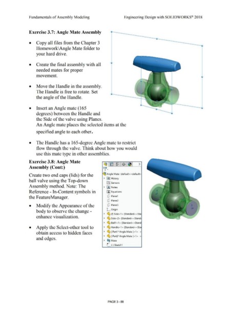
Exercise 3.7: Angle Mate Assembly
• Copy all files from the Chapter 3
Homework\Angle Mate folder to
your hard drive.
• Create the final assembly with all
needed mates for proper
movement.
• Move the Handle in the assembly.
The Handle is free to rotate. Set
the angle of the Handle.
• Insert an Angle mate (165
degrees) between the Handle and
the Side of the valve using Planes.
An Angle mate places the selected items at the
specified angle to each other.
• The Handle has a 165-degree Angle mate to restrict
flow through the valve. Think about how you would
use this mate type in other assemblies.
Exercise 3.8: Angle Mate ~1~1~1$ :~1 >
Assembly (Cont:) v-
Create two end caps (lids) for the ~ Angle Mate (default< <default>
> H£> I History
ball valve using the Top-down
lfrl Sensors
Assembly method. Note: The > fAI Notes
Reference - In-Content symbols in ~ Equations
the F eatureManager. dJ Plane1
dJ Plane2
• Modify the Appearance of the dJ Plane3
k Origin
body to observe the change -
~ ~ (f) Side<1> (Standard<<Sta1
enhance visualization.
> (9, Side<2> (Standard<<Standc
> (9, Ball1<1> (Standard<<Stand
• Apply the Select-other tool to > ~ Handle<1> (Standard<<Sta1
obtain access to hidden faces > ~ [ Part1 AAngle Mate ]<1 > - >
> ~ [ Part2" Angle Mate ]< 1> ->
and edges.
.-
~ ®@ Mate
L (-) Sketch1
PAGE 3- 88