
Page 255 - Subyek Computer Aided Design - [David Planchard] Engineering Design with SOLIDWORKS
P. 255
Engineering Design with SOLIDWORKS® 2018 Fund.amentals of Assembly Modeling
Point at the Center of Mass Insert Tools Window Help
Component . cr1J ~
~ Mate •.. ~ove Show Hidden A
ponent Components F
I!' Mate Controller...
Add a center of mass (COM) point to parts, assemblies or y
, VORKS MBD
Component Panern .. .
drawings.
r::iliil Mirror Components .. .
~ Smart Fasteners ...
11 e ti ,.
COM points added in component documents also appear in
~ ·' Exploded View ...
the assembly document. In a drawing document of parts or [. pl \ • <; t
GB Model Break View ...
assemblies that contain a COM point, you can display and ~ New Motion Study
reference the COM point. Assembly Feature
[ Referenc~ometry • gl Plane ...
•
·'
;-" Axis ...
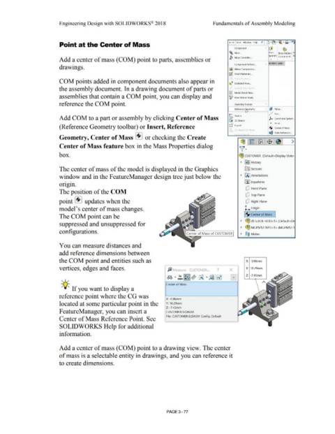
Add COM to a part or assembly by clicking Center of Mass C Sketch )-. Coordinate System ...
L 30 3D Sketch
• p·
01nL.
(Reference Geometry toolbar) or Insert, Reference rtJ} Layout ·$· Center of Mass
r ·,r 1 c n P'o1 "
10
ql Mate Reference ...
, ·1· , I .; l ,
Geometry, Center of Mass + I or checking the Create
~1~ 1~1$ 1 ~ >
Center of Mass feature box in the Mass Properties dialog
\(·
box. ~ CUSTOMER (Default<Display State-
~ ~ I History
The center of mass of the model is displayed in the Graphics lfll Sensors
window and in the F eatureManager design tree just below the ~ 00 Annotations
• • Ef:I Equations
or1g1n.
dJ Front Plane
The position of the COM
dJ Top Plane
point + I updates when the dJ Right Plane
model's center of mass changes. L Origin
The COM point can be 1·$· Center of Mass
~ ~ (f) GUIDE-ROD<1 > (Default<Di
suppressed and unsuppressed for
~ ~ MGPM12-1010<1 > (MGPM12-1
configurations.
~ ®@ Mates
You can measure distances and
add reference dimensions between
the COM point and entities such as X: -0.06rnrn
vertices, edges and faces. fj Measure - CUSTOMER... ? X Y: 18.29rnrn
~ ·~"m ~Yz ~ Ci! · ~ ~ 0 Z: -7.45rn rn
, ,/
Center of Mass
-;Q;. If you want to display a
reference point where the CG was
X: -0.06mm
located at some particular point in the Y: 18.29mm
Z: -7.45mm
F eatureManager, you can insert a CUSTOMER.SLDASM
File: CUSTOMER.SLDASM Config: Default
Center of Mass Reference Point. See
SOLIDWORKS Help for additional
information.
Add a center of mass (COM) point to a drawing view. The center
of mass is a selectable entity in drawings, and you can reference it
to create dimensions.
PAGE 3- 77