
Page 251 - Subyek Computer Aided Design - [David Planchard] Engineering Design with SOLIDWORKS
P. 251
Engineering Design with SOLIDWORKS® 2018 Fundamentals of Assembly Modeling
, 1 /
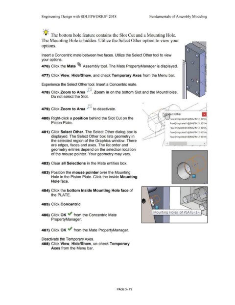
-;Q::. The bottom hole feature contains the Slot Cut and a Mounting Hole.
The Mounting Hole is hidden. Utilize the Select Other option to view your
options.
Insert a Concentric mate between two faces. Utilize the Select Other tool to view
your options.
476) Click the Mate ~ Assembly tool. The Mate PropertyManager is displayed.
477) Click View, Hide/Show, and check Temporary Axes from the Menu bar.
Experience the Select Other tool. Insert a Concentric mate.
478) Click Zoom to Area p . Zoom in on the bottom Slot and the MountHoles.
Do not select the Slot.
{-'\~
479) Click Zoom to Area ~ .., to deactivate.
II
~ect Other
480) Right-click a position behind the Slot Cut on the
. · · ~VFace@lmported1@[MGPM12-1010;
.
Piston Plate. Face@lmported1@(MGPM12-1 010i
Face@lmported1@(MGPM12-1010~
481) Click Select Other. The Select Other dialog box is Face@lmported1@[MGPM12-1010-;,
displayed. The Select Other box lists geometry in Face@lmported1@[MGPM12-1010~
the selected region of the Graphics window. There -
>
are edges, faces and axes. The list order and / l.,, /I
geometry entries depend on the selection location
of the mouse pointer. Your geometry may vary.
482) Clear all Selections in the Mate entities box. •
483) Position the mouse pointer over the Mounting
Hole in the Piston Plate. Click the inside Mounting
Hole face.
484) Click the bottom inside Mounting Hole face of
the PLATE. _ ... ..-.-,-......
--- \ \ I
'
Jf_;-"
485) Click Concentric.
...
Mounting Ho es of PLATE<l >
486) Click OK ~ from the Concentric Mate
PropertyManager.
487) Click OK ~ from the Mate PropertyManager.
Deactivate the Temporary Axes.
488) Click View, Hide/Show, un-check Temporary
Axes from the Menu bar.
PAGE 3 - 73