
Page 252 - Subyek Computer Aided Design - [David Planchard] Engineering Design with SOLIDWORKS
P. 252
Fundamentals of Assembly Modeling Engineering Design with SOLIDWORKS® 2018
Fit the model to the Graphics window.
489) Press the f key.
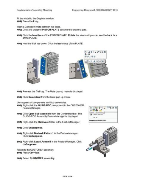
Insert a Coincident mate between two faces.
490) Click and drag the PISTON PLATE backward to create a gap.
491) Click the front face of the PISTON PLATE. Rotate the view until you can see the back face
of the PLATE.
492) Hold the Ctrl key down. Click the back face of the PLATE.
~ · d , ,<'> l"~~~
· ·~
~ J§> J> (B~
- -- ·- ......
Q O O 1~1 ~ -1. ej H Ll ~
,.. -~
•
I
\ (') 0
• •
• • •
493) Release the Ctrl key. The Mate pop-up menu is displayed.
494) Click Coincident from the Mate pop-up menu.
Un-suppress all components and Sub-assemblies.
495) Right-click the GUIDE-ROD component in the CUSTOMER
FeatureManager.
496) Click Open Sub-assembly from the Context toolbar. The
GUIDE-ROD Assembly FeatureManager is displayed.
Go To ...
Component (GUIDE-ROD)
497) Right-click the Hardware folder in the FeatureManager.
498) Click UnSuppress.
499) Right-click DerivedLPattern1 in the FeatureManager.
Click UnSuppress.
500) Right-click LocalLPattern1 in the FeatureManager. Click
UnSuppress.
Return to the CUSTOMER assembly.
501) Press Ctrl+Tab.
502) Select CUSTOMER assembly.
PAGE 3-74