
Page 231 - Subyek Computer Aided Design - [David Planchard] Engineering Design with SOLIDWORKS
P. 231
Engineering Design with SOLIDWORKS® 2018 Fundamentals of Assembly Modeling
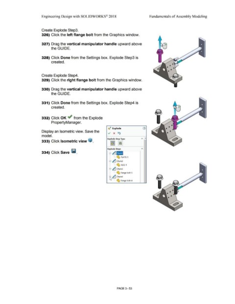
Create Explode Step3.
326) Click the left flange bolt from the Graphics window.
327) Drag the vertical manipulator handle upward above
the GUIDE.
328) Click Done from the Settings box. Explode Step3 is
created.
Create Explode Step4.
329) Click the right flange bolt from the Graphics window.
330) Drag the vertical manipulator handle upward above
the GUIDE.
331) Click Done from the Settings box. Explode Step4 is
created.
332) Click OK ~ from the Explode
PropertyManager.
e
~ -· Explode G)
Display an Isometric view. Save the
../ x t1)
model.
Explode Step Type A "'
333) Click Isometric view ~ .
~ ~
Explode Steps A
334) Click Save Ii.
s tJIIII
--- ~ PLATE-1
B tJ chain2
'
~ ROD-1
8--tJ Chain3
~ flange bolt-5
t tJ chain4
--- ~ flange bolt-4
PAGE 3 - 53