
Page 227 - Subyek Computer Aided Design - [David Planchard] Engineering Design with SOLIDWORKS
P. 227
Engineering Design with SOLIDWORKS® 2018 Fundamentals of Assembly Modeling
I Activity: Address - Tolerance and Fit
Locate the dimension in the FeatureManager.
298) Expand GUIDE from the GUIDE-ROD FeatureManager.
299) Double-click Guide Hole from the FeatureManager to
display the dimensions.
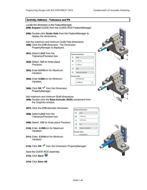
Add the maximum and minimum Guide Hole dimensions.
300) Click the 010 dimension. The Dimension
PropertyManager is displayed.
301) Select Limit from the
Tolerance/Precision
Tolerance/Precision box. ...0 1 v
~··
1.SO Limit Q') 1 ()
302) Select .123 for three place + I 0.01Smm I
Precision. - I O.OOOmm
I
.0 1 v]
.• ,
x.xxx [.123
303) Enter 0.01 Smm for Maximum
'·"" [ Same as nominal v]
1.SO
Variation. • .)CX
Primary Value A
304) Enter O.OOOmm for Minimum I D1 @Sketch3 •
I
Variation. •
110.ooomm 1:
305) Click OK ~ from the Dimension
PropertyManager.
Add maximum and minimum Shaft dimensions.
306) Double-click the Base-Extrude (ROD) component from
the Graphics window.
307) Click the 01 O diameter dimension.
Tolerance/Precision A
+,01 v
tSO I Limit
308) Select Limit from the -.ot ,
Tolerance/Precision box. + 1-o.oosmm I
- I -0.014mm I
309) Select .123 for three place Precision. .o,
x.xxx v
.o, [.123
....
....
31 O) Enter -0.005mm for Maximum 1.SO I Same as nominal v:
Variation.
Primary Value A
D1 @Sketch1
311) Enter -0.014mm for Minimum
Variation.
312) Click OK ~ from the Dimension PropertyManager.
Save the GUIDE-ROD assembly.
313) Click Save lli.
314) Click Save All.
PAGE 3- 49