
Page 222 - Subyek Computer Aided Design - [David Planchard] Engineering Design with SOLIDWORKS
P. 222
Fundamentals of Assembly Modeling Engineering Design with SOLIDWORKS® 2018
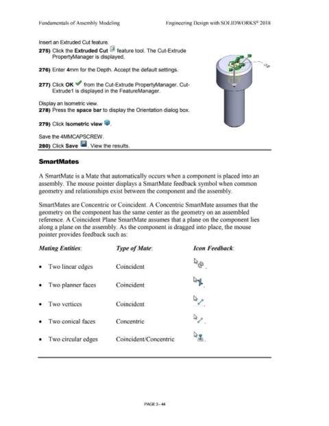
Insert an Extruded Cut feature.
275) Click the Extruded Cut I feature tool. The Cut-Extrude
PropertyManager is displayed.
276) Enter 4mm for the Depth. Accept the default settings.
277) Click OK ~ from the Cut-Extrude PropertyManager. Cut-
Extrude1 is displayed in the FeatureManager.
Display an Isometric view.
278) Press the space bar to display the Orientation dialog box.
279) Click Isometric view ~ .
Save the 4MMCAPSCREW.
280) Click Save Ii. View the results.
SmartMates
A SmartMate is a Mate that automatically occurs when a component is placed into an
assembly. The mouse pointer displays a SmartMate feedback symbol when common
geometry and relationships exist between the component and the assembly.
SmartMates are Concentric or Coincident. A Concentric SmartMate assumes that the
geometry on the component has the same center as the geometry on an assembled
reference. A Coincident Plane SmartMate assumes that a plane on the component lies
along a plane on the assembly. As the component is dragged into place, the mouse
pointer provides feedback such as:
Mating Entities: Type of Mate: Icon Feedback:
• Two linear edges Coincident •
• Two planner faces Coincident •
• Two vertices Coincident •
• Two conical faces Concentric •
• Two circular edges Coincident/Concentric
PAGE 3 - 44