
Page 218 - Subyek Computer Aided Design - [David Planchard] Engineering Design with SOLIDWORKS
P. 218
Fundamentals of Assembly Modeling Engineering Design with SOLIDWORKS® 2018
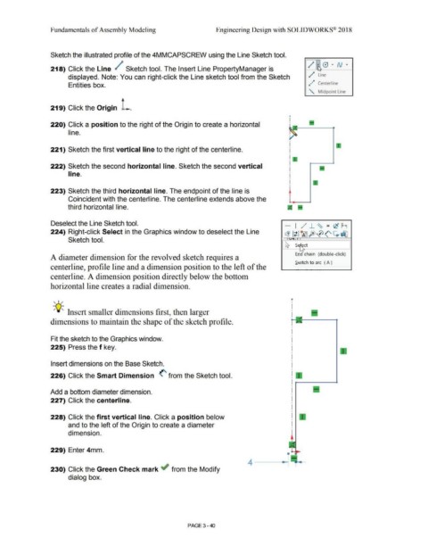
Sketch the illustrated profile of the 4MMCAPSCREW using the Line Sketch tool.
/ • 0 • N • '
218) Click the Line / Sketch tool. The Insert Line PropertyManager is I'
.
displayed. Note: You can right-click the Line sketch tool from the Sketch / Line
Entities box. d ,,P Centerline
" Midpoint Line
219) Click the Origin L.
•
I
220) Click a position to the right of the Origin to create a horizontal •
line.
221) Sketch the first vertical line to the right of the centerline.
222) Sketch the second horizontal line. Sketch the second vertical
line.
223) Sketch the third horizontal line. The endpoint of the line is
Coincident with the centerline. The centerline extends above the
third horizontal line.
Deselect the Line Sketch tool. - I /,/ J_ ~ - (C M
-
224) Right-click Select in the Graphics window to deselect the Line
~ lt liA5fe>0<' ~d]J
Sketch tool. . . ' I
~ ~ ct
I,,
Enc chain (double-click)
A diameter dimension for the revolved sketch requires a
Switch to arc ( A )
centerline, profile line and a dimension position to the left of the
centerline. A dimension position directly below the bottom
horizontal line creates a radial dimension.
, ,/ '
I
I
-;Q~ Insert smaller dimensions first, then larger I
I
dimensions to maintain the shape of the sketch profile.
Fit the sketch to the Graphics window.
225) Press the f key.
Insert dimensions on the Base Sketch.
226) Click the Smart Dimension (' from the Sketch tool.
Add a bottom diameter dimension.
227) Click the centerline.
228) Click the first vertical line. Click a position below
and to the left of the Origin to create a diameter
dimension.
229) Enter 4mm.
230) Click the Green Check mark if from the Modify
dialog box.
PAGE 3- 40