
Page 215 - Subyek Computer Aided Design - [David Planchard] Engineering Design with SOLIDWORKS
P. 215
Engineering Design with SOLIDWORKS® 2018 Fundamentals of Assembly Modeling
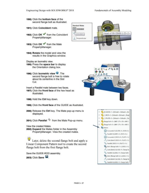
190) Click the bottom face of the
second flange bolt as illustrated.
Standard Mates
191) Click Coincident mate.
.ff Coincident
•
' •
192) Click OK ~ from the Coincident ' Coincident
PropertyManager.
I I I Perpendicular
193) Click OK ~ from the Mate
PropertyManager.
194) Rotate the model and view the
results in the Graphics window.
Display an Isometric view.
195) Press the space bar to display
the Orientation dialog box.
~a '"® !e ~~ ~
~·~~
196) Click Isometric view ~ . The .---.I ~ fe) b ® ei
second flange bolt is free to rotate [/\Jtdj_l~I H 1~1
about its centerline in the Slot
Cut.
Insert a Parallel mate between two faces.
197) Click the front face of the hex head as
i II ustrated.
198) Hold the Ctrl key down.
199) Click the front face of the GUIDE as illustrated.
-
200) Release the Ctrl key. The Mate pop-up menu is
~ ~ (f) GUIDE<1> (Default<<Default>_Dis
displayed.
~ ~ (-) ROD<1> (Default<<Default>_Displ
~ ~ (-) PLATE<1 > (Default<<Default> _Dis1
201) Click Parallel ~ from the Mate Pop-up menu.
~ ~ flange bolt<1 > (M8-1.25 x 30<<M8-1.
~ ~ flange bolt<2> (M8-1 .25 x 30<<M8-1.
View the created Mates.
®@ Mates
202) Expand the Mates folder in the Assembly
@ concentric1 (GUIDE<1 >,ROD<1 >:
PropertyManager. View the created mates.
~ Parallel1 (GUIDE<1 >,ROD<1 >)
, 1 / (Q) Concentric2 (ROD< 1 >,PLATE< 1 >)
-;Q;. Later, delete the second flange bolt and apply a /\_ Coincident1 (ROD<1 >,PLATE<1 >)
Linear Component Pattern tool to create the second ~ Parallel2 (ROD<1 >,PLATE<1 >)
flange bolt from the first flange bolt. ~ Slot1 (flange bolt<1 >,GUIDE<1 >)
/\ Coincident2 (GUIDE<1>,flange be
Save the GUIDE-ROD assembly. ~ Parallel3 (GUIDE<1 >,flange bolt<·
203) Click Save Ii. ~ Slot2 (flange bolt<2>,GUIDE<1 >)
/\ Coincident4 (GUIDE<1 >,flange be
~ Parallel4 {GUIDE<1 >,flange bolt<:
••
PAGE3 - 37