
Page 210 - Subyek Computer Aided Design - [David Planchard] Engineering Design with SOLIDWORKS
P. 210
Fundamentals of Assembly Modeling Engineering Design with SOLIDWORKS® 2018
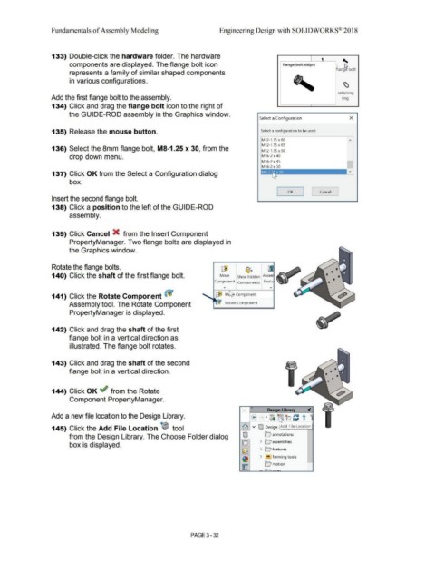
133) Double-click the hardware folder. The hardware
components are displayed. The flange bolt icon flange bolt.sldprt '
lang~ bolt
represents a family of similar shaped components
in various configurations. I \)
retaining
Add the first flange bolt to the assembly. nng
134) Click and drag the flange bolt icon to the right of
the GUIDE-ROD assembly in the Graphics window.
Select a Conf igurat ion x
135) Release the mouse button. Select a configuration to be used
M12-1.75 x 80
"
M12-1.75 x 85
136) Select the 8mm flange bolt, MS-1.25 x 30, from the M12-1.75 x 90
drop down menu. M16-2 x 40
M16-2 x 45
I
M16-2 x 50
137) Click OK from the Select a Configuration dialog
box.
OK Cancel
Insert the second flange bolt.
138) Click a position to the left of the GUIDE-ROD
assembly.
139) Click Cancel X from the Insert Component
PropertyManager. Two flange bolts are displayed in
the Graphics window.
Rotate the flange bolts. lIJ) ~
140) Click the shaft of the first flange bolt. Move Show Hidden Asse
Com~onent Components I Fea~
141) Click the Rotate Component ~ ~ M Component
Assembly tool. The Rotate Component Rotate Component
PropertyManager is displayed.
142) Click and drag the shaft of the first
flange bolt in a vertical direction as
illustrated. The flange bolt rotates.
143) Click and drag the shaft of the second
flange bolt in a vertical direction.
144) Click OK ~ from the Rotate
Component PropertyManager.
Add a new file location to the Design Library.
145) Click the Add File Location ~ tool ~ v ifflJ Design Add File Location
from the Design Library. The Choose Folder dialog iffll ~ annotations
box is displayed. o > 0 assemblies
lzs~ > Q features
~ > '!!'! forming tools -
~ O motion
. I i
PAGE 3 - 32