
Page 213 - Subyek Computer Aided Design - [David Planchard] Engineering Design with SOLIDWORKS
P. 213
Engineering Design with SOLIDWORKS® 2018 Fundamentals of Assembly Modeling
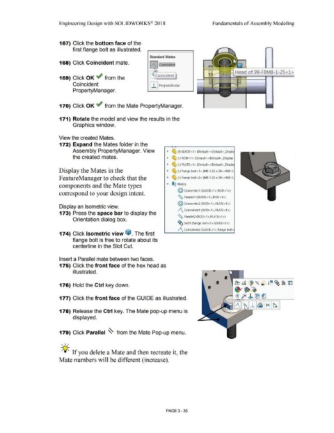
167) Click the bottom face of the
first flange bolt as illustrated.
Standard Mates
168) Click Coincident mate. Jt Coincident
Head of 99-FBMB-1-25<1>
169) Click OK ~ from the ' Coincident
Coincident I I I Perpendicular
PropertyManager.
170) Click OK ~ from the Mate PropertyManager.
171) Rotate the model and view the results in the
Graphics window.
View the created Mates.
172) Expand the Mates folder in the
Assembly PropertyManager. View • ~ (f) GUIDE<1 > (Default< <Default> _Displa
the created mates. • ~ (-) ROD<1 > (Default<<Default> _Display
• ~ (-) PLATE<1> (Default<<Default>_Displa
Display the Mates in the • ~ (-)flange bolt<1> (M8-1.25 x 30<<M8-1.
F eatureManager to check that the • ~ (-)flange bolt<2> (M8-1.25 x 30<<M8-1.
components and the Mate types ... ®@ Mates
@ concentric1 (GUIDE<1 >,ROD<1 >)
correspond to your design intent.
~ Parallel1 (GUIDE<1>,ROD<1>)
@ Concentric2 (ROD< 1 >,PLATE< 1 >)
Display an Isometric view.
/'\_ Coincident1 (ROD<1 >,PLATE<1 >)
173) Press the space bar to display the
~ Parallel2 (ROD<1>,PLATE<1>)
Orientation dialog box.
~ Slot1 (flange bolt<1>,GUIDE<1 >)
/'\ Coincident2 (GUIDE<1 >,flange bolt<
174) Click Isometric view G:a. The first
flange bolt is free to rotate about its
centerline in the Slot Cut.
Insert a Parallel mate between two faces.
175) Click the front face of the hex head as
i II ustrated.
• •
•• ~· ~~
176) Hold the Ctrl key down. • e?d ~~ ® !~ ~~ ~
~ ~ fe) J. tB (lJ
177) Click the front face of the GUIDE as illustrated.
(3 ~_i~ Hb.
178) Release the Ctrl key. The Mate pop-up menu is
displayed.
179) Click Parallel ~ from the Mate Pop-up menu.
, ,,,.
;Q~ If you delete a Mate and then recreate it, the
Mate numbers will be different (increase).
PAGE 3-35