
Page 216 - Subyek Computer Aided Design - [David Planchard] Engineering Design with SOLIDWORKS
P. 216
Fundamentals of Assembly Modeling Engineering Design with SOLIDWORKS® 2018
, 1 /
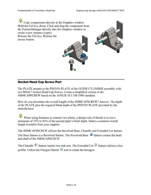
-;Q~ Copy components directly in the Graphics window.
Hold the Ctrl key down. Click and drag the component from
the FeatureManager directly into the Graphics window to
create a new instance (copy).
Release the Ctrl key. Release the
mouse button.
Socket Head Cap Screw Part
The PLATE mounts to the PISTON PLATE of the GUIDE CYLINDER assembly with
two M4x0.7 Socket Head Cap Screws. Create a simplified version of the
4MMCAPSCREW based on the ANSI B 18.3.lM-1986 standard.
How do you determine the overall length of the 4MMCAPSCREW? Answer: The depth
of the PLATE plus the required blind depth of the PISTON PLATE provided by the
manufacturer.
, 1 /
-;Q~ When using fasteners to connect two plates, a design rule of thumb is to use a
minimum of 75% to 85% of the second plate's blind depth. Select a common overall
length available from your supplier.
The 4MMCAPSSCREW utilizes the Revolved Base, Chamfer and Extruded Cut feature.
The Base feature is a Revolved feature. The Revolved Base ~ feature creates the head
and shaft of the 4MMCAPSCREW.
The Chamfer 0 feature inserts two end cuts. The Extruded Cut l&J feature utilizes a hex
profile. Utilize the Polygon Sketch 0 tool to create the hexagon.
PAGE 3 - 38